Sparepart
 RHOCaR Member
-
Posts
301 -
Joined
-
Last visited
-
Days Won
14
Recent Profile Visitors
2,154 profile views


Sparepart's Achievements
")
Wheely good builder! (4/6)
39
Reputation
-
I have changed a pinto cam belt, but not for a while. I know I have the splined bit that fits the tensioner spring bolt somewhere, BUT where did I put it! ... So many spiders are now homeless in my attempts to locate that strip of 4 or 5 splined sockets/bits....... so I need to buy some more ..... but now I look on-line and am amazed by the number of different splined sockets/bits available, I don't mean different makers, I mean different standards. The one the block that I have looks like it has 12 points, then I see 3 different standards of 12 point splines (at least) depending on the angle between the teeth. I did find a set of bits handed down from my father, but when I tried the one that looked the right diameter it started to go in but was obviouly the wrong tooth angle because it started to make grooves on the sides of the bolt teeth. I searched our extensive database and found the link below, however apart from telling me that a hex key might be ok, there is no definitive information abount exactly the type of splined bit needed. Does anyone here know the details ? https://www.rhocar.org/index.php?/forums/topic/25924-cam-tensioner/
-
I did this last autumn without this problem, following the manual as you have. Perhaps the seal has not gone into the housing all the way, and might be wedged out so that it is fouling the inside surface of the flange ?, or might have been proud and has now been pressed in by the flange and just needs to be tapped in a bit further.
-
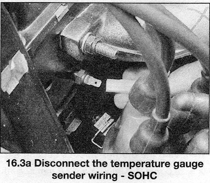
Yes, you are correct, I attach a snap from the manual.

-
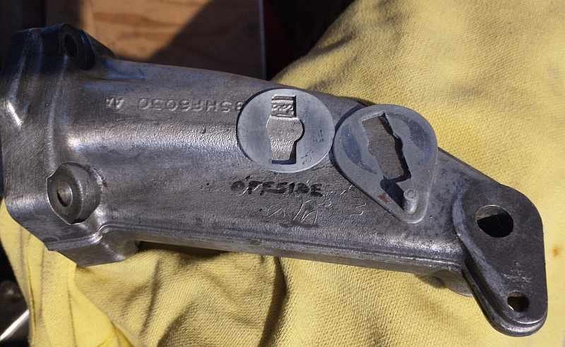
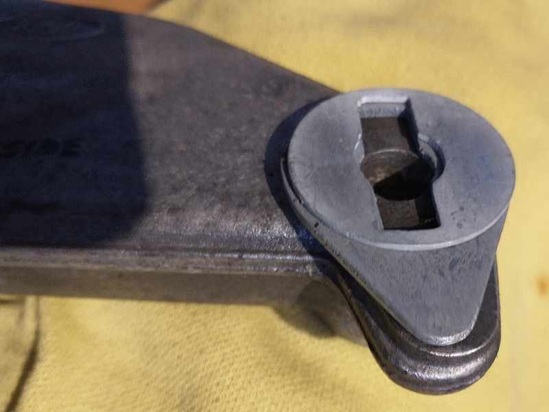
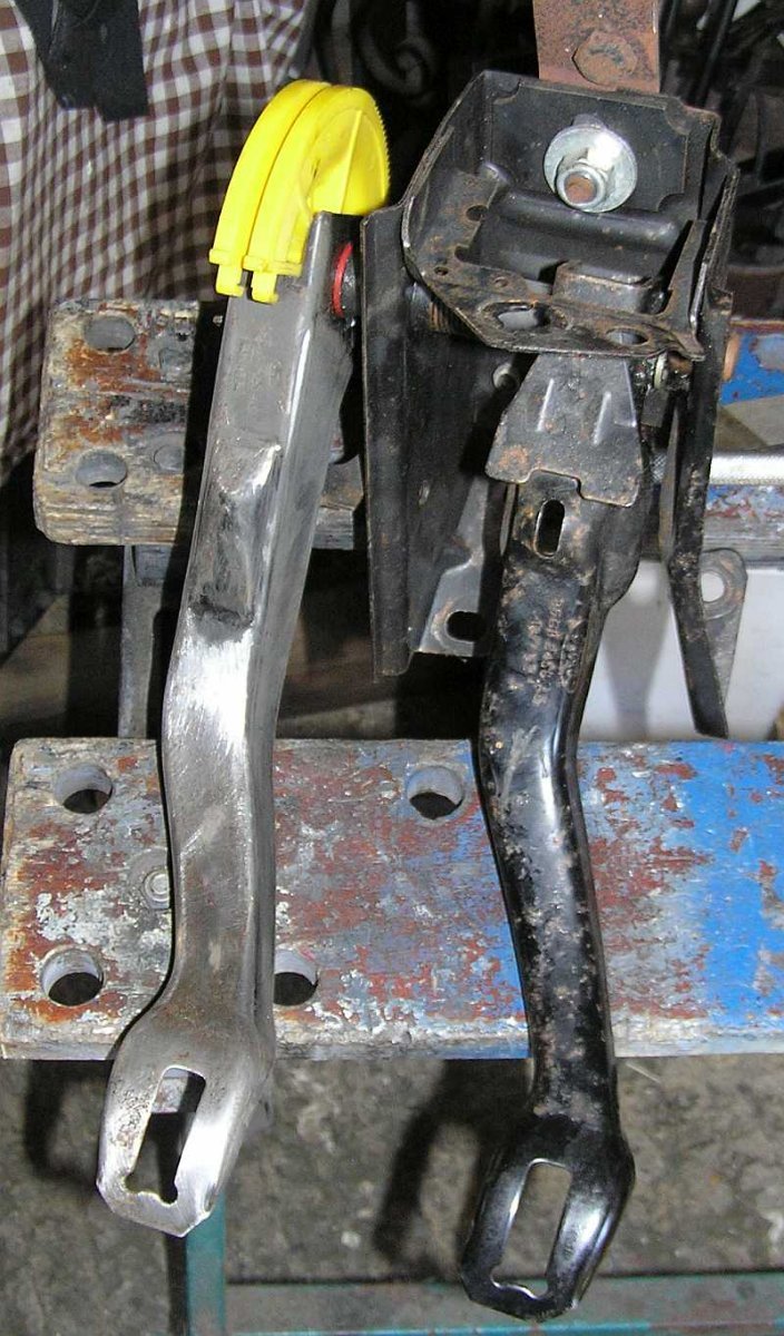
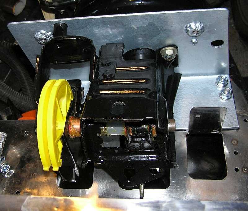
On the Mk1 Sierra (at least mine) the engine support arms do not have a slot. They use a special washer and spacer that fits over the bar in the mount and slots into a hole in the support arm. This means that there is no twist on the bolt in the rubber part when tightened or loosened. I attach two photos below that show the washers and the arm.
-
There is nothing special about your Ford Pinto engine, so just Google for advice on starting an engine for the first time after having been silent for a while, it's simple stuff like making sure the oil is clean and up to level, water in the cooling system, clean fuel in the tank and pipework to the carb etc..... take the plugs out and turn it over on the starter first see if oil pressure is enough to turn off the warning light.. check you even see a spark at the plugs, check that the timing belt is okay. As for the missing master cylinder, your Sierra servo doesn't look too good, rather than trying to get a Sierra master cylinder, you might consider ditching the servo and fitting a Ford KA master cylinder. Members have done this. Just use this sites search facility and search for "ford KA" (in quotes) and you will see the posts relating to this. As for identifying which 2B you have check out the page we have on identification at https://nw.rhocar.org/htm/identification.htm . The 2B build video is on Youtube at https://www.youtube.com/watch?v=DNA1Zs8jY_I
-
This is a suggestion, ive not tried it. Firstly use a long straight edge, say length of baton between scuttle top and nosecone edge to measure how much clearance you actually have. Then look at at thin universal pancake filters, like https://www.ebay.co.uk/itm/311892226985 to use. Such a filter could even be made thinner by trimming the sponge and cage, but obviusly too thin will strangle the carb. The other challenge will be to find a way to mount it on the carb. You could cut a round hole a bit smaller, say 20mm, than the inlet diameter, then cut lots of radial slots round the circumference, 10mm deep, then bend each out at right angles. This would let the filter base slot over the carb inlet with a jubilee clip around the all the bent down bits to fix it to the carb. Perhaps some tape around this would then make an air tight seal. The filter could be mounted upside down so that the dome nuts are underneath, leaving a totally smooth upper surface.
-
Bit late to this topic.... I attach a couple of snaps from my car. The second is the standard pedals, to see the standard spacing, yours look to have an offset brake pedal, but that could be perspective. The first is from above with the pedals installed. You see that the throttle is seperate, not installed, so could be moved easily in all directions. What is not easy is changing the height or spacing of the clutch/brake pedals. The clutch quadrant position is fixed by the release mechanism in the cable guide, and the brake pedal top by the alignment of the master cylinder rod. Moving the whole assembly up is theoretically possible, with spacers, but the whole top cover (not shown) would need to be raised, all the brake pipes extended, and then not so high as for the servo or fluid reservoir to hit the bonnet. Lowering the floor and/or altering the pedals is going to be easier, although shortening pedals will of course alter the leverage and range of motion somewhat, e.g. shorter clutch pedal would be harder to release smoothly.
-
Oh, just look at the S7 build manual, (I have an Exmo) and there is a small difference, the routing of the S7 cable looks to be through the sloping panel as shown in the build manual that I attached before in a different thread https://www.rhocar.org/index.php?/forums/topic/50972-s7-handbrake-cable/#comment-413125
-
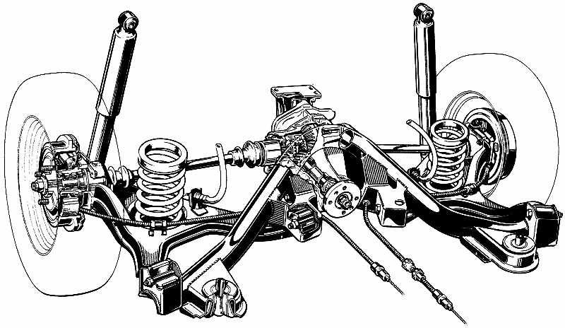
Have a look at this diagram, of the Sierra rear subframe from above. See, the cable route is pretty much symmetric, left to right. From the wheel backplate on top of the trailing arm and then through a hole in a flat plate part of the subframe really close to the pinion UJ (not shown here), so you have to imagine the prop shaft between the loop in the cable, out of frame bottom right to the pinion flange (shown). On the Sierra the nylon adjusters use a bracket from the body, but on your car the adjusters use the aformentioned holes in the flat part of the subframe. Out of frame there is an exposed loop of inner cable that goes through a metal yoke. The centre of the yoke is attached to a single rod that goes to the bottom of the handbrake. When the handbrake is applied the yoke moves forward and tightens the cable, if the yolk is properly lubricated any difference in L/R tension will be equalised by the cable slipping through the yoke. Because the cable is shorter than the one shown here, the yoke will be really close to and just above the prop and UJ, just inside the hole through which the prop appears from the transmission tunnel. If you use the "cut the cable in the middle" method of fitting then whatever you use to rejoin the ends has to fit in this restricted space between where the cable comes through the subframe and the yolk, without fouling the UJ or preventing enough slippage through the yolk to equalise the R/L tension. If you shorten by removing one of the end pips, then you have to be very careful to pre thread the items along the length of the cable before you weld on the new pip. Hope this helps.
-
Something in your description of where the wires go, does not sound good to me. Unfortunately you don't say which wire is + (I'm assuming black) and so green is -ve which would match the colours used in a standard sierra loom. The way a coil works is that with ignition on, and engine not running (and points closed if you are using points) then the +ve should be live via the ignition and the -ve should run to earth but not directly, it must run to earth via the ignition module (or points). In this state the low tension windings in the coil are energized and there is magnetic energy in the coil core. When the engine is running, the ignition module (or points) suddenly disconnect the -ve from earth, this causes a suddend collapse of magnetism in the core, and the energy is dissapated in the high tension coil, giving a high voltage pulse that is used for a spark. The dissconnection only last a short while, so that the coil can recharge with energy for the next spark ... and so on. So ... if the -ve connection on your coil is directly connected to earth, there will be no interruption in the circuit and so no spark. In the Sierra loom the black comes from the ignition switch, the green runs to the electronic ignition module, which then connects the coil to earth but intermittently disconnects when a spark is required, depending on all the other inputs to the ignition module.
-
Just browsed the parts catalogue, I think you need to purchase a Ford part that you will find by either using the number 1644433 or the code 83BB2A603AG, just put "Ford" in front and search with your favourite search engine should pull up a Sierra MK1 handbrake cable assembly..... then find the best price/quality etc.
-
I think that you need to buy a Sierra handbrake cable MK1 or Mk2 probably ok, because it will need to be shortened. There is no "off the shelf" part I am attaching a pdf of the three pages covering the handbrake, from the build manual. It is just about legible. S7-Handbrake-Build.pdf
-
I am wondering if you are checking your car against the IVA manual ? In the section on seat belts, there is the following:- Note 2: A suitable single bolt fixing of adequate strength would be, for example, a bolt of at least 11mm (7/16") diameter of grade 8.8 (the grade may not be shown on a bolt produced for a seat belt anchorage). Other bolt fixings may be acceptable providing they are of equivalent strength. Two adjacent seat belts may be secured by one bolt. In this case consideration must be given to the additional loads on the anchorage Just in case you have not looked at the IVA manual, HERE is a link to the current version (today 2023-10-14) on gov website.
-
Potentially there are three areas that might be preventing the drum from coming off the hub. One is the edge of the drum around the hub, in your photo this is the start of the rusty bit, the hub being black paint. Wire brush the rust off and apply penetrating oil (WD40) to the joint area. The next thing might be the wheel studs, which the drum has to slip over, again wire brush the base of these and apply penetrating oil. The third area is harder to free. The brakes are self adjusting, each time the the handbrake is applied, see the manual. It is possible for the shoes to be tightly sitting in a "trench" formed by wear and rust build up on the inside drum edge, stopping it from coming over the shoe surface. You can tell this is the case, if when you try to lever the drum off, carefully with a broad screwdriver or tyre lever between the drum edge and backplate it seems to be free at the hub and wheel studs but keeps springing back on to the hub when you let the lever go. In this case you should try releasing the shoes as described in the manual. My copy does not just say "remove the drum" there is the following "it is possible to release the automatic adjuster mechanism by inserting a screwdriver through the small hole in the drum and pressing down on the ratchet (see illustrations). .(5.5b)..... but I dont see a small hole in your drum, look for it. Your brake adjuster looks to have the locking mechanism missing, someone has put a lump of something there to stop it unwinding itself. Again look at the manual especially at the "hand brake equalizer" see figure 29.3. The cable has to slide through here easily to even out tension between both sides. And like IanS says the cable will have been shortened by cutting a piece off and fixing a new ferrule. The build video shows how to drill a hole in the center of a piece of bolt thread, put the cut end through and crimp using a cold chisel. Something like this might have popped off and the cable can now just pull out from the backplate on one side.
-
Just did a very quick search, loads of hits, this one most recent and looks to answer your questions. https://www.rhocar.org/index.php?/forums/topic/39046-cooling-system-diagram