LewisH
 RHOCaR Member
-
Posts
143 -
Joined
-
Last visited
-
Days Won
5
Content Type
Profiles
Forums
Events
Store
Community Map
Everything posted by LewisH
-
Don't worry, problem solved. Faulty TPS - serves me right for buying crap from ebay. If it seems to good to be true, it normally is.
- 1 reply
-
- 1
-

-
Afternoon all, I am in the process of converting from dizi to megajolt on Ford Pinto, but have come up against a problem when wiring the TPS. There are 3 pins to wire from the sensor, my understanding is that they should be identified as 1 = signal. 2 = ground. 3 = 5v. Can someone tell me how to test these to find out what is what? So far, I have connected a multimeter set to ohms x1k, one lead connected to centre pin (purple), the other connected to one of the other pins (grey or black). I am getting a high resistance between purple and black and a low resistance between purple and grey. If I connect grey & black the resistance isn't constant. Not sure if the above testing is the correct way to do it? Also, if I turn the throttle when the leads are connected, the resistance isn't changing, this is the same when measuring between any of the pins. I've tried taking the TPS off and turning by hand and get the same result. Any help on this would be much appreciated. For info, this is a Mikuni TPS fitted to ZX6R carbs.
-
Lovely stuff
-
dave@dampertech.co.uk
-
After a lot of messing around, checking timing, changing cylinder head, changing plugs, leads, rotor arm, dizi cap...I've finally found the source of my engine running problem. Frustratingly, after all that, it was just a blocked fuel filter on the carb. I've got a weber 32/36 and beneath the carb there is a 19mm brass nut, underneath the nut there is a small filter, which was full of black detritus. Never realised there was a filter there...now I do, cleaned and she now starts and idles just fine, hallelujah! Just in time for summer, oh bugger. At last, the upgrade to 2.0 and stage 3 head is complete, only took me a year.
-
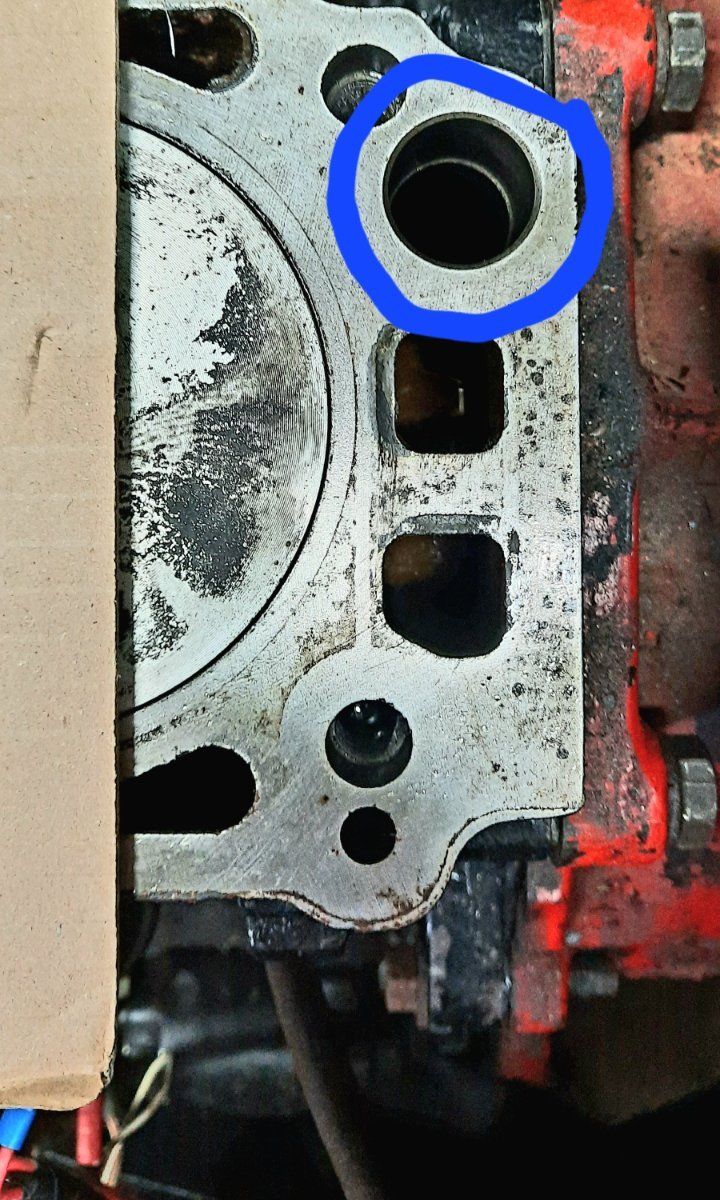
New head has arrived at last, but in taking the old head off I accidentally dropped one of the m6 bolts that holds the plate on the back of the camshaft down an oil-way in the block. I've tried fishing it out with a magnet but no joy. I assume it's now sitting in the sump...question is, do I need to take the sump off and get this out? Or can this sit in the sump without causing an issue? Pic attached of where the bolt has gone.

-
I have done this using these from kit card direct. They need a bit of modification but work well and allow wings to steer with the wheels. http://www.kitcardirect.co.uk/cycle-wing-bracket-front-wing-stays-for-billet-aluminium-upright-black-single.html The front suspension buttresses also need trimming a bit to allow the wing to sit across the width of the wheel.
-
So I've checked and double checked cam/ignition timing, it must be close enough to run. I've taken the carb off and given it a good clean, a bit gunky but not too bad...yet still I'm getting exactly the same issues. Very difficult to start and once running it won't idle and just dies. I'm now thinking is this potentially leaky valves on the head giving low compression? I've rebuilt the bottom end but didn't think to check how the valves were sealing. Given that this was an ebay engine purchase, probably should have checked this before slapping the head back on. I've got an injection head being refurbished/machined by Burtons at the moment, but was hoping to do the running in miles with the existing head whilst I wait for the refurbed one. Is there an easy way to check for vavle leakage without taking the head off? I don't know if my symptoms are a result of low compression but running out of ideas here.
-
I have a spare weber 32/36 auto choke with manifold. Came to me with a complete engine so I've never used it but looks in good condition. Let me know if you are interested
-
Oh. Looks like I have totally misunderstood the term "maximum lift on inlet valve". Doh! Thanks Richard, I'll give this a go tomorrow just in time for the great weather...
-
Yeah. Double checked this yesterday with gap figures when cold from Cam supplier
-
Thanks Steve, I'll double check cam timing with DTI. Pretty sure carb/fuel supply is OK because using same setup as was on previous engine.
-
Engine is built and installed, however, I'm having trouble getting it to start and run properly. It struggles to start, lots of coughing then finally fires but won't idle and cuts out. I suspect timing is out, but I've double checked everything and in my mind it is correct. I've changed HT leads, dizi cap & rotor arm but still the same. I have worked out cam timing by finding TDC, zero'ing timing disk, then turning crank clockwise until I reach 108 deg (FR33 cam), then setting cam at this point with inlet cam lobe on no1 cylinder pointing to the sky...is this correct? At this point the rotor arm is pointing to no1 lead. Any help or pointers to check much appreciated.
-
I could be interested. I'm only in Maidenhead, so there's a good chance the car would make it that far I'm yet to fire-up the newly built pinto though...so fingers crossed!
-
Sorry, just measured again and they are 38mm, not sure how I got 33, maybe digital calipers should have been on my Christmas list! Anyway, 42mm into a 38mm hole is going to be difficult. Do I just need to persist with a big hammer? Or are these plugs too big? I can only seem to find one size for pinto but I am a bit worried about cracking the block. From the little info online that i can find, plugs should be less than 1mm larger than the hole, but no idea if this is correct or a general rule of thumb?
-
I ended up getting some correct HC pistons, which are now fitted and flush with block. I am now pretty close to getting the engine back together, bottom end is all done, sump fitted. I am going to fit new core plugs and have purchased a set from Burtons, but they seem to large to me. I understand that it has to be an interference fit, but they seem way too big. The holes in my block are 33mm and the core plugs are 42mm. Is this right? The block is a 205, but it doesn't have the plug on the back of the engine near the flywheel. Not sure if this is a different type with smaller core holes? If the one's from Burtons are too big, does anyone know where I can get the correct plugs and what size they should be to match my 33mm hole? Thanks Lew
-
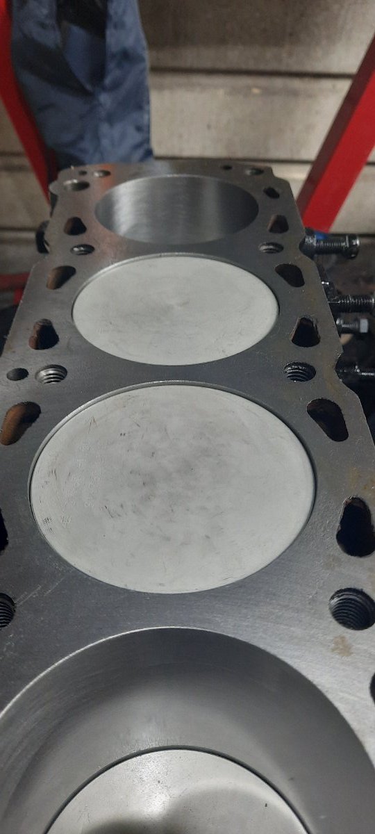
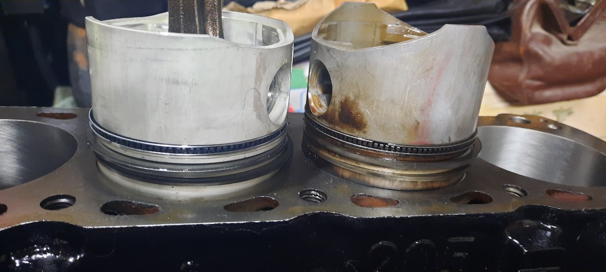
Block has been re-bored +1mm, new mahle pistons to suit, reused the con rods. Crank ground .5 mains & .25 big ends, put it all together yesterday but something isn't right. The pistons are still sitting 1.5mm below top of block when at top of stroke. I've tried contacting the company that did the work but discovered they have since closed the doors and gone under! Having spent nearly £2k on this so far, feeling a tad frustrated to say the least. My understanding is that the low compression engines had pistons sitting 1.5mm below block and standard were .5mm below. Can anyone confirm this? I was hoping to achieve 10.1 compression ratio, but with pistons sitting this low, I understand that this won't be possible. Question is, what should I do now? Skim the block face 1mm? Change rods to YB type? Buy another set of pistons? Not really sure which one is going to be the best option, considering cost and feasibility. Any advice much appreciated. Pics below of pistons at top and also side by side comparison of new vs old pistons.
-
Yes 42mm. I have installed mine in the nose cone at an angle with the top of the rad tilted back towards the engine. I don't have a header tank, just a bottle connected to the rad top for expansion. If you are doing this you need to make sure that the top of the rad is higher than the bottom of the cylinder head. I have also fitted an electric fan on the rear of the rad, just enough room here. To mount the rad I used some hinges attached to the top of rad to the front of the chassis, this allowed me to set the angle that I wanted without having to make a bracket to suit the angle. For the bottom rad mounts I used some threaded rods on either side, again, this allowed me to adjust the angle to suit the space. Then I used some thin aluminium sheet to block around the sides and underneath the rad so that all if the air is pushed through the rad and over the top into the engine bay. I don't have any overheating issues. Just got back from a long drive in 20+deg heat, sat in traffic no problem. If you need more info or pictures let me know.
-
OK so I've connected it up correctly now but when the sender float is at the bottom it is reading 1/4 tank, when it is at top it reads full, but anywhere in between it shows empty. Have I got a faulty sender unit or am I still doing something wrong?
-
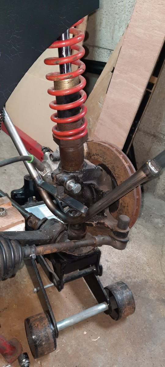
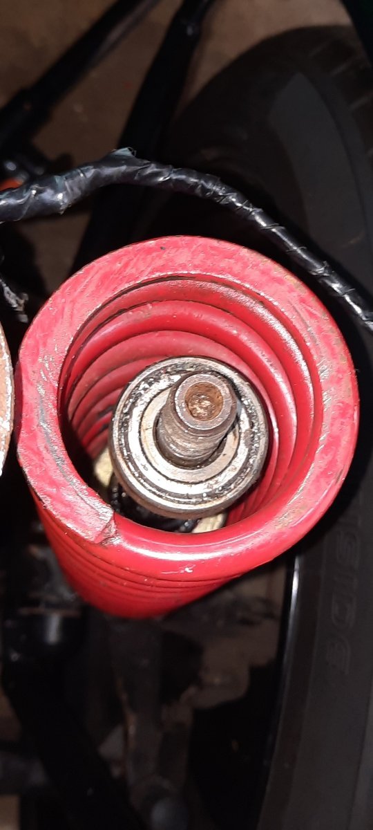
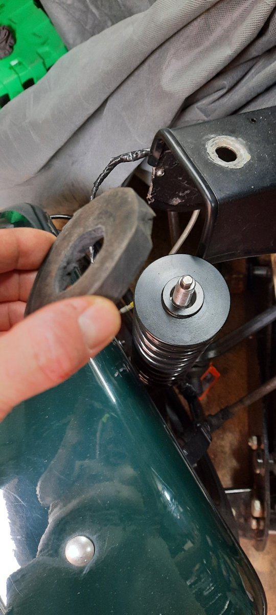
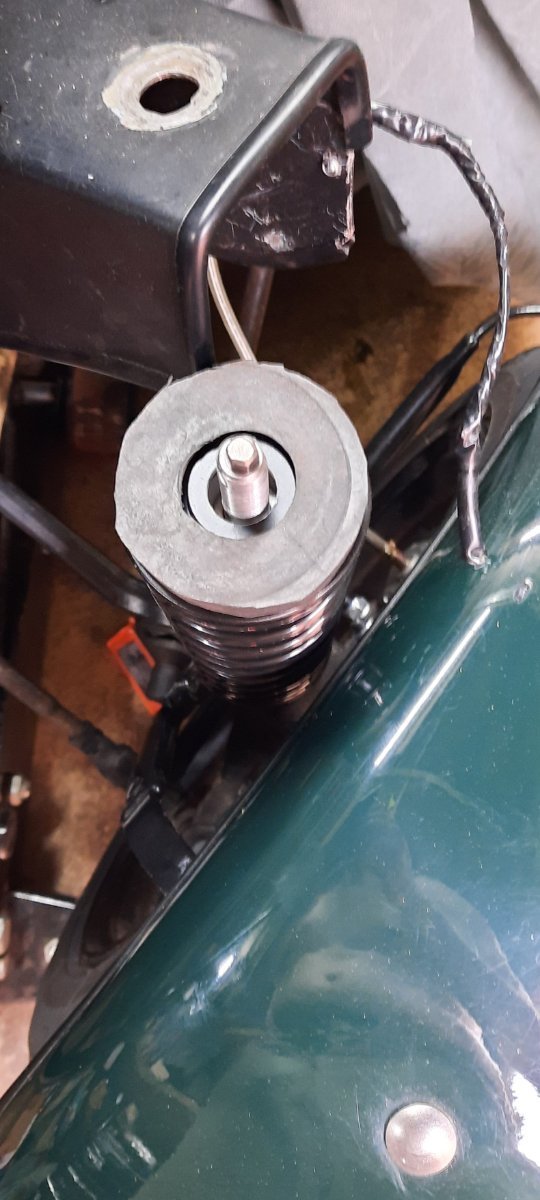
I have reused the bearing from the old RH setup for now, but I'm not convinced that this is the correct type of bearing to be used for this due to the type of load it is taking. Pic below of the bearing, is this a thrust bearing? It's just the spring seat that is adjustable.
-
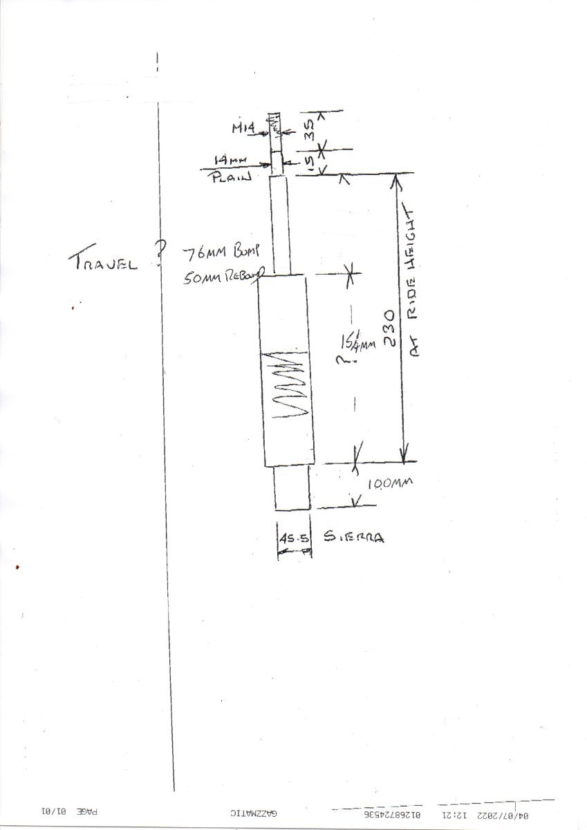
For any other Exmo owners that are interested, please see below the drawing for the struts. They were £300 for the pair of dampers, £50 for a pair of springs and £15 delivery + VAT £438. Forgot to mention above that they are also adjustable so we can play around with ride height and spring loads.
-
Tried to get the car running today and found my old sender unit had failed and now has a hole in the pipe as a weld had broken. I have a replacement sender unit but the wiring connection is different. My old type had a three pin plug, but the new type only has earth & stud for level sensor (same type you can but from kit spares). One of the three pins on the old type was a positive feed, which I assume is no longer needed, the other two I assume are level sensor and low fuel warning light? I have tried connecting the sender new unit to earth and on the main sensor stud I have connected each of the two wires in turn from the old wiring but no joy. I have 12v feed to my gauge, and don't really want to run a new wire from this to the sender unit...can anyone advise what I need to do here?
-
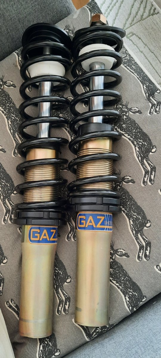
Good news! These arrived this afternoon from DamperTech. Have fitted one of them, looks good, fits but the spring is a tight fit under the buttress...as expected. I've also added a 10mm thick rubber ring that is fitting between the spring top mount and underside of the chassis. Wasn't happy with the ride on the previous spring/damper and seemed crazy to have a spring in direct contact with the chassis. Every mcpherson strut you look at has a rubber mount of some sort, haven't figured out a way of encasing the bearing in rubber yet, but this will hopefully be an improvement nonetheless. I'll fit the other one tomorrow and hopefully that'll be me back on the road again after a couple of months...fingers crossed!
-
OK thanks. ARP bolts it is then
-
Plugs, gaskets, seals and bearings all arrived today...dropping the block off re-bore tomorrow. The rods that came out of the block have F cast into them, not sure if that helps identify them?