Longboarder
 RHOCaR Member
-
Posts
8,200 -
Joined
-
Last visited
-
Days Won
70
Content Type
Profiles
Forums
Events
Store
Community Map
Everything posted by Longboarder
-
A pop from the exhaust means burning fuel in the exhaust. No more. Flame has to come from one of the cylinders. Confirms you have sparks and fuel. No more than that. I suggest you go back to basics and recheck the wiring of the supply to the coil. Try and confirm which is the trigger wire from ECU to coil 1. Confirm plug leads 1 & 4 are on that side of the coil. Confirm the 12v supply is on pin two the middle of the plug. Find TDC for cylinder 1 with a screwdriver down its plughole. Make a pointer the almost touches the crank pulley and mark pointer and pulley with tippex. Now you can use a strobe to confirm you have ignition at roughly the right position. Check your TPS or MAP/MAF is calibrated in your ECU map. Check fuel pressure if you can. Make sure your ECU map knows what fuel pressure and injectors it is running or correct these figures if they are wrong. Balance the throttle bodies by eye. If it still won't run then you need a visit from someone who knows Emerald
-
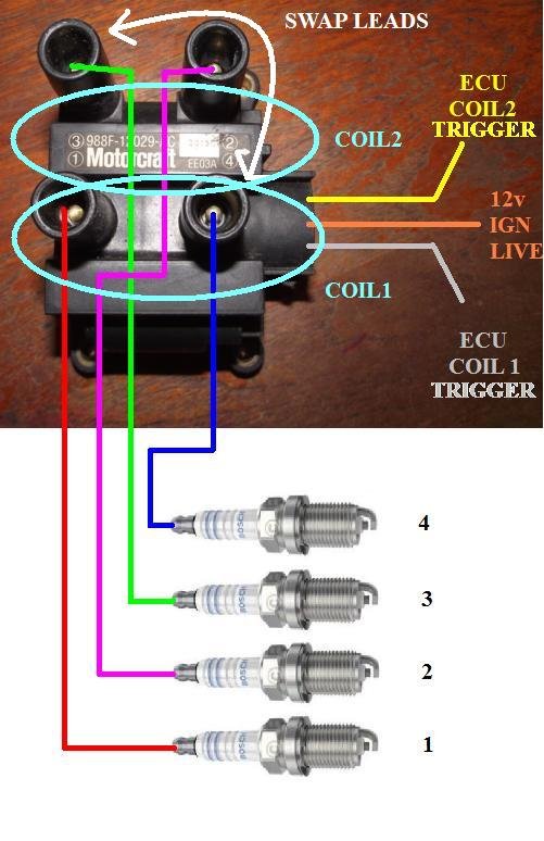
Can't do a pic. Mines ST170, omex and my own loom so nothing would match. However pic below is zetecish coil, and how it connects. Normal is three pin plug with an ignition live supply to the centre pin (2) direct from a nice clean stable ignition live supply from the loom, not taken from the ECU. Then the ECU supplies two coil trigger wires to pins 1 and 3 on the coils which fire each of the two coils alternately. Coil one sparks plugs 1&4 together each time it is triggered as pistons 1&4 approach TDC together. Now only one of those cylinders is going to be ready to fire. Say cylinder1 with a load of air and fuel and all compressed so that one goes bang and the spark from plug 4 is wasted as cylinder 4 is just finishing its exhaust stroke. However as the engine continues to turn a further 180 degrees piston 3 will be completing its compression stroke full of air and fuel and the ecu will trigger coil two which will spark plugs 2&3. 3 will go bang but spark 2 will be wasted on a cylinder just finishing its exhaust stroke. Another 180 degrees and the ECU triggers coil one which fires plugs 1&4 again. This time its bang for cylinder 4 and the spark in 1 is wasted. Another 180 degrees and its 2 that goes bang and 3 is wasted, everyone's had a go and we are back to the beginning. I doubt you have a wiring error. Quick check is swap the coil to plug leads for plugs 3 & 4 at the coil end as per the arrows on my pic. Yours may not be quite the same parts but the jobs just that swap and then try to run the engine.

-
Job for next winter then! Get on with that bodywork for now. Waiting for the next instalment!
-
Which bit are you correcting? I could/should have said check spark plug lead 4 is with spark plug lead 1 on one bank of the coil etc but my posts are too long already and I assumed the OP would read it that way. So Ophdir check you have the spark plug leads correctly positioned in the coils. The zetec coil is actually two coils. If you look carefully at its upper surface you will see numbers for the leads, 1,2,3,4. You will note 1 & 4 are together to one side of the electrical plug/socket on the coil, and 2 & 3 are together on the opposite side. The fact that you noted exhausts 1 & 2 were warm suggests that these two cylinders were firing some but as they are not on the same coil it proves both coils were firing some but 3 & 4 exhausts didn't get hot so cylinders 3 & 4 were not fired.This led me to suggest that although you appear to have plug leads 1 & 2 correct you might have plug leads 3 & 4 on the wrong posts on the coils which would mean the fire at the wrong timing to make a bang. You shouldn't have a zetec flywheel on wrong as the bolts are unevenly spaced and it will only fit on the crank in one orientation.. Further, after you have checked you have the plug leads on correctly I would stop worrying about sparks and look at fueling.
-
Sorry. My car is a New 111 monocoque, front outboard springs at 45 degrees, rears coilover in the pan and vertical. Should have stated the desired spring poundage was in the region of 120 for the fronts, 200 for the rears. RH supplied 180 for the fronts which was way too hard for the monocoque Threes and 180(?) for the rears which was a little soft for the rears. Combined with the very poor zimmeride shocks which did little to control them and wore out quickly. On a series of bumps on my second drive after building, the rears on my car pumped down and bottomed out so I was riding on the bump stops. I should correct myself on desired poundage for the rears. I'm trying to remember back a ways (MAC was April 2000) when I fiddled with springs and shocks and can't remember these days what I had for breakfast let alone these sorts of details. The 'pumping down' ride was memorable. I concluded rear springs too soft and too little shock resistance on bounce and too much resistance for the weak spring on rebound. 200lb rears came next then 250, combined with AVO shocks all round set softish. Much better. I did buy a set of 300lb rear springs but never fitted them so I was obviously satisfied at that stage. Better shocks are vital. For a 3A with inboard shocks 100 to 120lb fronts, tending toward the softer as the compression is more linear. Rears 250lb but if you tend to carry a passenger or are heavier than my 11 stone then perhaps more. The above is my experience with a new 111. It doesn't apply to 2B or current cars with very different geometry. Better spring weights and shocks were needed and some experimentation. To the OP the rear should not be harsh. Check you are running a ride height that has the shock still extended two thirds (when car is loaded) so you do have suspension travel available. If the shock is compressed more than that then bumps will take it down to the bump stops which is harsh. Duck I recall the sierra springs were too short and too soft. I don't know the rate. I don't know where your top spring mount is or where your shock attaches. If you could fit coilovers in place of your current shocks then that would be one way to go.
-
Aftermarket or original springs? If they are the original RH ones then they are too hard. 120 on the front and 180 to 200 on the rear depending on shock position/suspension design. Some have the springs in the trailing arm pan(200) and some on the original shock mount position(180).
-
Assuming you are using aftermarket ECU and wasted spark zetec double coil and you have shown some firing on 1 & 2. As 1&2 are on separate banks of the coil you have proved sparks to some extent. Check that 4 is with 1 on one bank of the coil and 3 is with 2 on the other bank. Yes you can get a jolt touching/holding an HT lead when the engine is turning over or running. What fueling are you using? What ECU? What Map? Yes you might need to fiddle with the map, assuming it's a start-up map for a 2.0 zetec, at least to check it's set for your injectors and fuel pressure and cranking advance is only about 5 deg BTDC.
-
Which are what on a seven? Cruise economy on a shopping car perhaps. It adds nothing on a seven. I would ditch the vacuum advance and block the vacuum take-off for it. Never used it on my pinto. I removed the unit from the bosch inductive dizzy and fixed the baseplate so it wouldn't move. Just ran on the mechanical advance. Do another trial measure of advance against rpm without the vacuum advance and post it up. Check with accuspark if they advise you run it.
-
I believe the pressure relief valve lifts at around 5.5 bar setting the upper limit hot or cold. Haynes quote hot 3.7 to 5.5bar at 4000rpm. Lower above that due to the piston cooling jets opening. My gauge only shows 4bar at 4000rpm hot. I think you still don't have a complete electrical circuit running your gauge. No idea where the break is.
-
How many terminals are there on the sender? For example mine has three. One to the gauge, an earth and one to the oil warning light. Some senders have a built in low oil pressure warning light as well as the sender for the gauge.
-
I would do this with the wheel off but the nuts back on and nipped up.A dial gauge on a heavy stand is the standard method for checking runout. Gives you an actual figure and a nice visual representation as the needle moves too and fro if the disc is warped. Failing that make a rigid frame from wood with a big nail sticking out to touch the disc face and weight it down ++. You thus have a fixed point sitting say a foot off the ground. Move the frame till the tip of the pointer is a couple of thou away from the disc face. Get your best glasses on and watch for an opening and closing gap between pointer and disc as you rotate the disc. If it remains in contact all the way round tap the frame further from the disc a few thou and spin again. Careful observation and you should see a tiny gap which ideally remains constant as you spin the disc. You could use feeler gauges at closest and furthest gap to get an idea of runout. Bit Heath Robinson but would give you an idea.
-
Is the shoe auto adjuster free moving and setting in new position when released. The ratchet teeth on them wear/corrode sometimes and don't 'set' the new position. Don't see why that would affect the other brakes apart from a slightly longer pedal. Does the front left come direct from the master cylinder or share with other lines? Have you checked run out of the left front disc itself or its thickness at intervals round the rim? Either of these could cause a snatch while rotating leading to locking up. I would be tempted by a new pair of discs and pads if there is doubt.
-
Neat way of holding in the centrecap but presumably the standard studs and bolts are under it. Have you examined a wheel to check that the offset is correct (my original steel wheels were ET41) and they have a ford centre bore or suitable hubcentric spacers? When driving is the steering effort acceptable? Does the steering self centre at all/slightly/strongly if you let go of the wheel after a turn? These points are more to do with suspension set-up that can have an effect on steering effort. Does the car have a quick rack? That would increase effort. 13 inch steering wheel seems about right for most people. I wouldn't go bigger than 14 even with a quick rack.
-
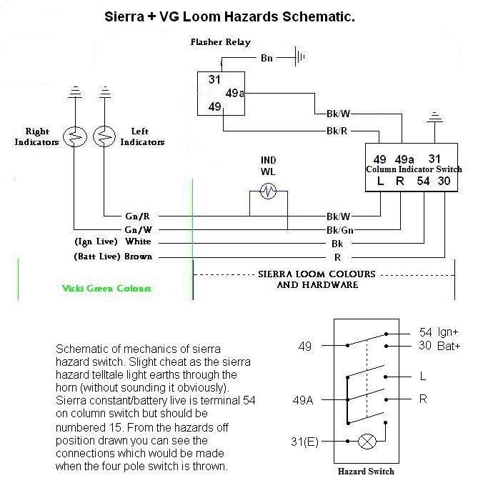
Been away hunting the sun. GBS looms are plug and pray. I don't know how they test them or if! Basic info and you will then have to work from there. Hazards use a constant live supply into the column plug pin 30. Indicators use an ignition live supply into the column plug pin 54. If the hazard switch is ON a constant live goes out from column pin 49 to indicator relay pin 49. If the hazards are OFF (and ignition is on!) an ignition live supply goes out from column pin 49 to relay pin 49. If hazards are off and ignition is off pins 49 will be zero volts. This is regardless of what's going on 'downstream' of the relay. (Testing relay output from pin 49a is problematic as some relays will not function without the correct load. More modern relays are not load dependant.) (The relay also has an earth pin 31.) Potential output from relay pin 49a returns to the column switch pin 49a and goes nowhere unless the indicator is used to send it to L or R circuits which of course are separate. When the hazards are switched on supply to the relay pin 49 is switched from ignition live to constant live, L and R indicator circuits are linked together and output from pin 49a is switched to both these now linked circuits. Found an old pic with Sierra and VickiGreen colours which may not be your colours but the circuits should still be the same. If all the indicator lights flash with hazards ON the relay is probably OK. Hazard switches have been sticky in the past so some contact cleaner or WD40 might help. It does sound as if ignition live output from column pin 49 may be suspect. Check column pin 54 is live with the ignition ON. Early switches part numbers start 83BG and later ones 87BG or 92BG but I don't think it matters in this case unless the pin layouts are different. Relevant pin numbers are the same.
-
Zetecs sometimes don't suck up oil if they have been left 'dry' for a while and the oil pump is empty. Result is long crank on dry bearings and possible damage. This happened to me with a new blacktop engine and still no oil pressure! I simply cut a suitable tin can in half and stuck it in place of the oil filter as a reservoir. Took off the cam cover and lubed the cams. Took out the plugs and put about 5ml of oil down each bore. Then filled the tin can reservoir with oil and wound the engine back a few rotations on the crank nut. (Gave reverse flow of oil to the oil pump.) Then replaced oil filter and pressure came up quickly.
-
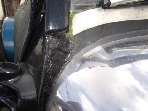
A problem with the monococque cars is the top of the scuttle is unsuported and flexible. When I built I thought the best solution was to suport it and make it non-flexible! Full width angle iron bolted up on the underside of the scuttle where the screen mounts. The frame RH supplied had the longer piece a tad too long so when I bonded the screen in the frame I trimmed it so its lower edge was resting onthe scuttle. I know some taller members left the 'legs' on to get more height but downside is a bigger gap to fill. I refitted my screen last autumn as the original sikaflex from 2001 had unstuck from the scuttle. Lasted 17 years so not bad! Sorry about the algae in the pic but the car lives outside.
-
Burlen do SU pumps, carbs and Amal carbs.
-
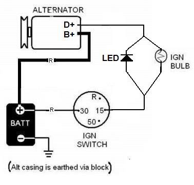
Type six needs more excitatory current to terminal D+ than an LED can supply, even if the LED is the right way round! Thus as has been suggested you need to run a resistor in parallel with the LED. A suitable resistor is an old fashioned ignition light bulb, 12v 5w. Crude pic below.
-
The park switch unclips from the wiper body and disassembles too.
-
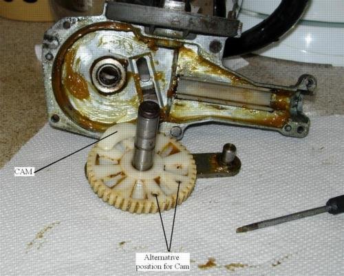
You can just see the cam in the picture. You can also see the biggish elongated hole in the ally body of the wiper that a little plunger from the park switch sticks through. If this cam was missing or the switch was missaligned or the plunger was broken off then the wipers would be constant.
-
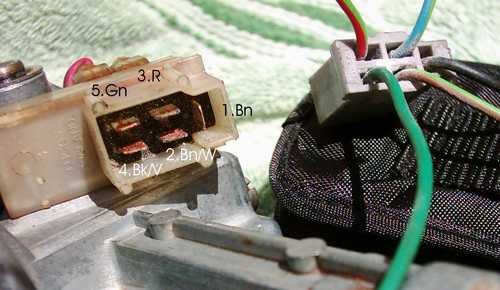
I'm confused. The earth goes on Term.1, Parklink Term.2, (Connects to 31B1 on column switch) Park power Term.4, (a live 12v either constant or ignition live) Fast Term.3, (Connects to 53B on the column switch) Slow Term.5, (Connects to 53 on column switch) With the ignition on and wipers switched off and parked there should be zero volts at 1,2,3,5, but 12v at 4. The terminals are numbered as below in the pic. Note where the numbers are for the plug or the socket. One is a mirror image of the other. The only likely faults the park switch in the little white box on the motor could have are the contacts stuck together so that the motor gear cam cannot open them, or the said cam being missing. Either of these would cause constant running. You can check all the wire continuities. Previous post gave you all the switch continuities to check. Pic below. Ignore the printed on colours. They were sierra loom colours. The only live wire goes on terminal 4
-
A question which should be asked. What alternator have you got or more specifically what does the connector on the alternator look like. Daniel Brookes post shows examples. https://www.rhocar.org/index.php?/forums/topic/47403-alternator-led/ Many modern non lucas alternators need an ignition live and an alternator/ignition lamp.
-
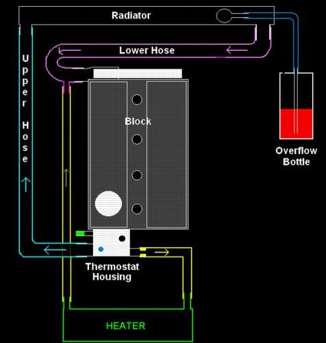
This is mine. Includes warm-up bypass to reduce stress on the engine. Use the zetec thermostat housing if you can. This copes with 200bhp engine.
-
Not a logical conclusion I'm afraid. When you feel the inclination and have a bit of spare time get the scales out and weigh the corners. (On level ground and with 70KG in the driver seat)(It's surprising that there should only be 1/2 a kilo side to side with the driver onboard)
-
Is it trying to suck through an injection micro-filter? Minimal inline filter only needed and I would have put it close to the rear of the tank and low as poss.