GambolGold
 RHOCaR Member
-
Posts
163 -
Joined
-
Last visited
-
Days Won
1
Content Type
Profiles
Forums
Events
Store
Community Map
Everything posted by GambolGold
-
Do you still have the calipers?
-
Thanks for the responses. Its clear what I need to do - or not do.
-
Or, in this case "Parking Charge Notice". I stayed too long in an Aldi car-park, which is overseen by ParkingEye. This is because I took my family for a meal in a local pub before shopping in the Aldi, which ironically, took our stay 15 minutes over the 'allowed' 1 1/2 hours. A few days later I received the Parking Charge Notice for £70 (reduced to £40 if paid by 16th May). I would gladly pay my 'dues' if I was confident I am legally obliged to or broke the law. - I did not have to pay for a ticket - There is clear and adequate sign-age around the car-park telling you of the 'contract' (?) you enter into by parking your car there. - I stayed more than the displayed allotted time (1 1/2 hours) - I will be more careful next time Its a fair cop guv'! Or is it? I hesitated to fork out to ParkingEye because several sources indicate the Parking Charge Notice is something not legally enforceable, but disguised as something that is. Having looked ParkingEye up on old forum entries on Money Saving Expert - as well as other material - the consensus is: ignore it, its a hoax, ParkingEye survive because some people just pay up, it will go away. Well I'd like to get a up-to-date answer in case laws have changed over the last few years Etc. so I am asking here, Do I pay up (a fair cop) or do I ignore it (a new calliper for the Hood or tyre for the tin-top)? Thanks for taking the time to read this.
-
Holes for mounting the circuit board in the box need 'adjusting' with a small round file - I must find one.
-
 Hi, Its good to be back. I've been working on the ignition kit intermittently and have got as far as fixing the circuit board in the box. Just a few items of caution - obvious to some people reading this, but were not obvious to me when I started sand therefore may be useful to others at my level of experience and skill: 1. mark out the circuit-board-fixing-holes in the bottom of the aluminium box before you start to solder any components as the board will lie flat on the box surface and holes can be marked more accurately. 2. Watch out for three-pinned components. They caught me out. I'd soldered one in the wrong place and had to remove it to correct the error. 3. The wire colours seem to be different in the kit to the diagrams. You might want to buy 'correct' coloured wires too.
 -
Finished soldering componetns onto circuit board for PIC-chip-driven programmable ignition module. Next: external wires, mount it all in a box, then then the adventure of getting it to work will begin. - oh and must pay my subs for 2011.
-
Its mentioned in February edition of Practical Classics. Apparently it was developed because a family of VW enthusiasts out-grew its original camper-van.
-
I can't say I "recomend" it yet - because I have only just got the kit my self but I intend keeping the folks on this forum updated with how it goes on. Read this series of posts: Programmable Ignition System Mk2 - An Electronics Kit! It seems cheap and serious at the same time. QED
-
Welcome back and have a great Christmas!
-
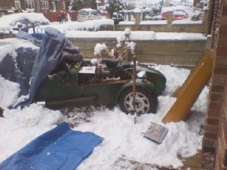
Ah there is nothing to compare with winter motoring, or changing clutch cables in the snow. Just park it on compacted snow and dig a bit of a little cave-thing under your car for easy access to the clutch arm underneath!

-
Apparently, because its an inductive discharge type of distributor (which sounds confusingly similar to 'inductive ignition system'), it has a 'reluctor', the four-pronged magnetic bit that rotates. It is therefore also referred to as a 'reluctor distributor'. (The bits that create the signal are also called an 'inductive type pulse generator' too). Yep, you guessed it: I've been reading books today ('The Bosch Automotive Handbook' & 'Automobile Electrical and Electronic Systems') - oh and got some help form the Everyday Practical Electronics forum people too! So now I know which diagram to follow in the instructions. I'll let you know how I get on.
-
Before I start putting hot solder anyway near anything that resembles part of a car, I need to make sure I'm following the right diagram. I have 6 circuit diagrams for different ignition set-ups. My distributor has 2 wires coming out of it and therefore I am inclined to believe it is actually a Bosch inductive discharge system. This is contrary to what Grim said, but then he did not know the number of wires as my photo did not include this detail unfortunately. The Hall effect sensor requires three wires. Am I right so far? The circuit diagram options are given the following headings: A. Points or ignition module version (one trigger input "from points or ignition module") B. Engine management trigger version (one "trigger signal 0-5V") C. Reluctor version (two inputs) D. Hall effect / Lumenition version (three inputs) E. Crane optical version (three inputs to do with LEDs' and photodiodes) F. Piranha optical version (three inputs to do with LEDs' and photodiodes) Which one should I choose? I eliminate E and F because those are optical. I eliminate D. (?) because its a Hall effect system. I'm left with A, B and C. C, the Reluctor has two wires, but so could the others if I wired wire two to the chassis. Any help to source the required information will be greatly appreciated. Thanks for reading.
-
Yes, you've got it, I'd like a mappable system and somthing more accurate than the current mechanical vacuum advance. Thanks for your interest. By the way Grim has told me things about my system I did not know, does anyone know a reliable source of information so I can read up on my existing system, such as how the advance works with no bob-weights etc?
-
I just want to verify something here. I believe I have a pre 1987 distributor - Bosch inductive discharge. Is this correct (photos below)? Am I right in thinking this is an amplifier (called an electronic ignition module in Haynes)? : I am thinking of bunging (i.e. skillfully connecting with reliable automotive connectors) my completed kit between the two components: distributor and 'electronic ignition module' - of cause disabling the bob-weights. (I like Longboarders idea of doing away with the dizzy altogether by the way, but that will have to come later on for me). Is my little plan sound so far? Thanks for reading this and regards.
-
Apparently you can use it to modify an existing 'signal' (if that's the right term for the low voltage impulse from the dizzy/points) to the coil - if my interpretation of what you said as "add control to the distributor" is correct. Or you can disable the bob-weigths, vacuum advance Etc. and this module will fire the coil via an amplifier Etc. doijng all the calculations itself. My carburettor is the standard Webber down-draught 32-36. I'm still toying with the idea of a separate MAP sensor or to fit the one in the module kit.
-
No, I'm not convinced either. I wont be until Its build, installed, set-up and thoroughly tested. But its the finding out that's the fun bit, isn't it? And I don't mind sharing my experiences with fellow Robin Hood fans. The kit cost £27.50, then there was about £5 postage on top of that. Thanks for the Megajolt link. Regards.
-
Hi Woolly, Here are the 'Specifications' as stated in the magazine (take your pick Everyday practical Electronics September to November 2009 (British) or Silicon-chip March to May 2007(Australian): Timing adjustment resolution: 0.5 degrees resolution advance and retard. Timing adjustment range: plus or minus 60 degrees for 12-cylinder engines, plus or minus 90 degrees for 8-cylinder engines, plus or minus 120 degrees for 6 cylinder engines, plus or minus 127 degrees for less than 6 cylinders. Using less than 75% of the limit is recommended to prevent timing "drop-out" with sudden Rpm changes. Timing adjustment accuracy (above low RPM setting): .2% for a 2-cylinder 4-stroke. 0.3% for a 6-cylinder 4-stroke, 0.4% for an 8-cylinder 4-stroke (note: 0.3%is equivalent to 0.12% at 40 degrees advance or retard for a 6-cylinder engine). Timing update: the update period is the time between successive firings. Timing calculation period: 700 micro seconds maximum. Timing jitter: plus or minus 5 micro seconds at 333Hz (5 microseconds is equivalent to 0.3 degrees for a 6-cylinder engine at 10,000 RPM). Minimum input frequency: 0.6Hz (corresponds to 36 RPM for a 2-cylinder 4 stroke engine, 18 RPM for a 4 cylinder 4-stroke engine Etc). Maximum input frequency: 700Hz (corresponds to 14,000 RPM for a 6-cylinder 4-stroke. Cylinder settings: 1-12 cylinders for a 4-stroke engine and 1-6 for a 2-stroke engine. Minimum RPM setting: 0-25,500 RPM in 100 RPM steps. Maximum RPM setting: indirectly set by RPM/SITE -- 0-25,500 RPM in 100 RPM steps. Minimum load setting: 0-255 in steps of 1(corresponds to 0-5V). Maximum load setting: indirectly adjusted by changing loads per site (255 in steps of 1). Debounce adjustment: 0.4ms or 2ms. Dwell adjustment: 0-25.3ms in 0.2048ms steps (multiplied with voltage below 12V). Dwell variation with supply: x1 for > 12V, x2 for 9-12V, x3 for 7.2-9V, x4 for <7.2V. Firing edge selection: low or high. Spark duration: 1ms. Map setting: two 11x11 maps (MAP-alpha and MAP-beta) or single 15x15 map. Knock input range: 0-5V (1-1.25V = no retard; 1.25-5V = progressive retard in 16 steps). 9 degrees at 3.75V, 12 degrees at 5V for 1 degree resolution; 4.5 degrees and 6 degrees respectively for 0.5 degree resolution. Knock monitoring (required an additional knock circuit): monitored for the first 6ms after firing. This period is reduced at higher RPM with the start of dwell. Optional 4000 RPM 0r 6000 RPM sensing limit. Ignition retard activation (when enabled) is set for a minimum of 10 sparks with the onset of knocking. Internal test oscillator: 4.88Hz. Response to low RPM setting: 0-25,500 RPM in 100 RPM steps. Typically set at around 1000 to 2000 RPM. I hope you can make something out from the above. The PIC chip is the '16f88 E/P' and comes already programmed. There is option to mount the MAP sensor (that's Manifold Absolute Pressure - not to be confused with all the other maps) on the main circuit-board. The module is programmed or set-up via a good old RS232 cable. A 'Hand Controller' is used to input the 'maps' (I just wonder whether its possible with a computer?). Other settings are introduced via a couple of 'jumpers'. The hand controller can be left attached and connected to the engine during driving to fine-tune the settings. The ignition module is KC5442 and the hand controller is KC5386 from Jaycar Electronics: www.jaycar.com.au The attached photos are: 1. the exterior of the ignition module, 2. the interior of it, 3. the exterior of the hand controller and 4. the interior of the hand controller. I hope this helps, any more questions form anyone, don't hesitate to ask.
-
Dear friends, An electronics magazine caught my eye one day in work - in particular an article on a programmable ignition kit. I started to read it and discovered it continued through two more issues. I eventually photocopied all three articles to study in more detail at home. Anyway, I ended up sending off for the kit which arrived a couple of week later from Australia. It includes all the components, including a substantial aluminium case and even some solder, and the cherry on the cake is the PIC chip (Peripheral Interface Controller), which performs all the calculations. It comes pre-programmed with memory for three ignition 'maps': two 11x11 maps which you can switch between while you are driving and a 15x15 map. It can be adapted to take input from a variety of signals: hall effect, reluctor, points Etc. Has anyone else had any experience with such a device? My plan is to do away with / ignore the bob-weight and vacuum advance mechanisms in the distributor, using it only to distribute the spark to the four cylinders, and to provide a trigger for this new-fangled electronics module. The new module will feed into the existing ignition amplifier, providing very accurate and rapidly-adapted ignition sparks. If anyone is interested I will gladly send more details, or even updates if you are as enthusiastic as I am.
-
100 with standard 2l pinto, 4 speed gear-box, running at 6000 rpm. So maybe if you did a retrial in 4th gear you could get more. Mine weighs 740 kg (heavy I beleive) and has a standard sized wndscreen. Yes, it can reach 70 quickly, then seems to hit an aerodynamic wall.
-
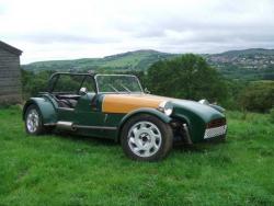
Greeting from Nat - formerly from Marple, Stockport, new father of 3 week old Hester. (Currently trying to convince my self it could be a family car with just a little adjustment.)
-
-
Thank you both for your interest, input and offers of help.
-
Hi, I'm raising this topic on behalf of a builder in the early stages. He has watched the DVD! He needs a bit of encouragement in these early stages of bewilderment. I am encouraging him to become a member too. I've attached a photo of part of the incomplete front end (i.e. just bottom wish-bones, no holes or mountings for a shock-absorber on the wish-bones, no top wish-bones, no shock-absorbers). Please: 1. advise what is needed to complete this front suspension (and whether available from the factory) 2. advise pitfalls to avoid 3. changes to the chassis so things will fit (e.g. cut, move, weld) OR please suggest links as I've a feeling this must have come up many times before and I've not managed to find it. Thanks for reading and regards, Nat
-
Ive been using just Xandros for a few years. I chose it because of its ease of installation. Its very reliable and quick to respond to your clicks. The computer does not get upset if you pull the plug - not that I do. But suppose you had a power cut, the computer would jsut bootup as normal. I can't install Corel software and doubt anyone can. It nets works with a Windows computer no problem at all - even for me, who does not know much about it. Good luck - you may not need too much of it though, NAt