itllbedonesoon
-
Posts
67 -
Joined
-
Last visited
Content Type
Profiles
Forums
Events
Store
Community Map
Everything posted by itllbedonesoon
-
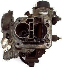
I think its a Webber 26/30 DFTH....got it from a scrap yard as it matched the bolt pattern on my manifold. I know its a small venturi but hopefully it will get me running. The pinto is running although idling very fast at the moment. I am currently checking for vacuum leaks and if that doesnt work I am going to try to retard the points dizzy a bit. I wanted to check that mysterious connection was not the reason I had a high idle speed. It is currently not connected to anything but the engine starts no problem, its just too eager. Any thoughts would be appreciated on this. thank you
-
Sounds important, should this be connected to something? Because I do not have an ECM module or anything to connect it to? should I have posted this in electrics section of the forum!!
-
Hi, Please could someone let me know what the electrical connector on the right hand side on the picture is for. Not the connection for the electric choke but there is another electrical connector that I have no idea what it is for? Any help would be appreciated. Thank you.

-
Hi, Thank you, wiggling and pushing did not work unfortunately and I have not been able to get the time to try disconnecting the gearbox end yet, but hopefully I will be able to soon. Fingers crossed.
-
Hello All, I have a MT75 gearbox and the matching speedo cable and clocks all of the same donor. It is fitted at the gearbox end and circlipped in place, however at the clocks end the cable will not connect. I have rotated the shaft on the clock connector so the square feed goes into the clock but no matter how much force is applied the cable will not go far enough onto the connection to allow the plastic clip to engage. With the amount of force I don't think the plastic clip would hold it anyway. Something is definitely not right....anyone any ideas please???
-
Shorted Wiper Now Blowing A Fuse - Help
itllbedonesoon replied to itllbedonesoon's topic in Electrics
Thank you for all the advice, I started again but this time starting from the fuse distribution terminal as you advised and followed that wire. It forked and I disconnected one of the forks further along the loom and checked for grounding on all the connections. It was grounding down the other branch, I followed this wire and it took me to the car horn switch in the steering wheel. The wire was grounding where is passes past the dash board and lies on top of the steering column and key barrel Ha ha!!! and unfortunately also the car horn was busted. I have ordered a new car horn and sorted out the grounding. So all good. I tested the horn circuit wiring in a bulb in place of the broken horn, all good and the wiper motor still works and no blown fuse! Although now my indicators have stopped working, I have hazards but no indicators. So I will try to look at this tomorrow. Thank you for sorting out my blown fuse as I have no idea with electrics and did not even know where to start. -
Shorted Wiper Now Blowing A Fuse - Help
itllbedonesoon replied to itllbedonesoon's topic in Electrics
ok, I checked the blue/green from the wiper motor tracing back to the column switches. Unfortunately (or fortunately depending on the circumstances) there is no bulkhead to transition between the wiper motor and the column switches and the loom is partially encased in ribbed sheathing (or was until i pulled it apart) so it would struggle to ground unless off another wire. While checking the wire I did a continuity check from the blue/green to earth and it was not showing as grounding. I checked the other wires from the wiper motor for grounding using continuity and the 12v live feed was earthing. This comes in to the wiper on a green from the VG loom and green I believe is pretty much the live circuit for all the ancillaries! I checked separately the washer bottle, foot brake switch and wiper motor and all were showing as grounding. I started tracing the green and low and behold, hidden in the tape in the loom it joined a cluster where it seems all the green wires in the loom are interconnected. I started separating them 1 at a time until I lost the earthing. I traced this green wire to the sierra instrument cluster. When I disconnect the green from the instrument plug connector, I lose the grounding in the the green wires. I disconnected the plug from the instruments and tested with continuity to earth all the wires. About 10 of the 12 are showing as grounding. However, now I am getting lost from seeing the forest because of all the trees, I guess a circuit has to ground at some point to complete the circuit back to the battery. I am worried now that the wires out of the instrument cluster are the return wires that is why so many of them are grounding with a continuity test even with the plug disconnected. I also tested the problem 15amp fuse terminals (with the instrument plug disconnected so my green circuit is not grounding) and the distribution terminal of the fuse is still showing as grounding. So this leads me to believe: 1. the grounding is not in the green circuit supply to the wiper motor. 2. It might be a fried column switch which is why so many circuits on the instrument panel appear to be grounding. 3. continuity testing to earth on the various circuits was not the right thing to do and I have confused myself. My bets are on No.3. I ran out of time but will try disconnecting the column switches and see how that affects the grounding on the instrument cluster connector and then I am out of ideas... -
Shorted Wiper Now Blowing A Fuse - Help
itllbedonesoon replied to itllbedonesoon's topic in Electrics
Thank you for the responses: The wiper motor is from a land rover i think, it is a lucas 5 pin worm drive gear type. It does not look like the connector comes off it appears attached to the wiper motor. I have tested the connections with a multimeter, Fuse supply terminal to earth = 12.57volts Fuse distribution terminal to earth = 0 volts I then disconnected the battery (as I read you are not suppose to check resistance on a live circuit?) connected the red multi meter to the fuse distribution terminal. all tests were done at the 200 ohm setting on the multi meter: fuse supply to earth = infinite fuse distribution to earth = 0.89 Column switches disconnected, connecting the distribution fuse terminal to the column switches connector wire as follows: Indicators & dip switch side to 54 = infinite to R = 0.90 to 30H = 0.2 X to 49 = infinite to L = 0.9 to 49a = infinite to 31 = 0.9 to 56a = infinite to 56b = infinite to 56 = infinite Wipers and lights switch side to 56 = infinite to 53.2 = 18.1 to 58 = 1.2 to 53c = 0.3 31b.2 = 18.1 to W = 0.4 to 30 = infinite to 53a = infinite 31b.1 = infinite 53 = infinite 54 = 18.3 53b = infinite Then testing the wiper motor wire with the column switches still disconnected: Earth = 0.3 Park = infinite fast = infinite 12v supply = 18.2 slow = infinite Unfortunately with very limited electrical experience I do not know how to interpret the figures as there seems to be varying readings in each column connector group and also up to the wiper supply wire? Thank you in advance for any further advice, -
Hi, When reconnecting my wiper motor I did not connect the live feed correctly, it came off at some point and shorted with one of the other terminals on the wiper motor or on the wiper body. Problem now is the 15 amp fuse on the loom keeps blowing every time I try to reconnect the battery. I am guessing the short from the wiper motor has done some damage somewhere creating a short to earth. I have the VG loom, which came with a 4 fuse holder, this is the 15 amp that keeps blowing. There are 3 relays and a 3 pin ford flasher unit. With the battery connected and no fuse I am getting constant live 12v to one side of the fuse with the ignition off. When I go to ignition 2 (15 amp fuse missing) I am getting no power to the sierra dash lights, the hazards don't work, wiper does not work. headlights do work. I have no idea how to find where the short is or how to go about tracing it through the myriad of wires under the dash. Can anyone please suggest a possible way to locate the problem (apart from looking in a mirror)? Thank you
-
mine are the ends with the 'V' tabs also. Thanks for the link, those gaitors seem pretty universal and lots of fords in the compatability list. Will go for them. Cheers all.
-
Hi all, Does anyone know what type of track rod ends were used on the 2b as i need to get some new gaiters? 1 of the gaiters has split. The ones i have were new from richard back in the day. are they sierra ones? cheers
-
Hi all, Just a quick question, can i cut the mini style 'wiper motor wire bit thingy' (think its called a worm gear)? or will it unravel once i trim the end off, as it is far too long to run out under the bonnet. thanks
-
thank you, thank you, thank you! The wiring was correct as per your original instruction, cheers Jez. The wiper motor was working, cheers Longboarder. It was a lack of power to the black/violet on the switches. thanks again Jez. (i had mixed up the green and the light green/black on the VG side going through the connectors onthe way to the switches. shhh... dont tell anyone). cheers John
-
also, just looking at longboarders diagrams on the NW site, i dont have my washer bottle connected up, does this matter?
-
Thanks Jez, unfortunately no joy, nothing happened. i tried it on fast slow and intermitent and got nothing on any of them. i also tried it with the motor casing earthed, nothing at all. As i was unsure of which way round to put the connections to the motor internal pin connections, i tried swapping the VG wires over on your listed pins 2 and 4 and ended up immediately blowing a fuse. Just to check i am not being an eedyit, i have only tried it with the ignition in position 2, so the elctrics are on. i am getting a live feed on the VG green but will the circuit work in ign position 2 or do i need to start the engine? if so, i guess: 1 - the wiper motor is duff (it is brand new) 2 - i still dont have the correct wiring 3 - i have a prob in the VG loom and/or stalk. 1 - Can anyone advise on how to test the wiper motor? Without knowing the wiper motor pin configuration i guess it is hard to, but if someone can advise how, i can give it a go. 2 - can the pins be identified by their continuity or resistance across the wiper motor? i have continuity across 2 pins and then seperately across 3 pins, with the 3 pins showing different levels of resistance between the 3, if this helps? 3 - when the system is live but not connected to the wiper motor, should i be getting live feeds on the VG slow and fast wires when i click the stalk or does everything need to be connected to make the circuit work? I have definately got live and earth on the VG side, should i be getting live readings from the other wires? cheers John
-
Hi, Can anyone help with the wiring for a land rover wiper motor to the VG loom (NielD, i saw u mention it in another post)? I have a landy wiper motor with a 5 pin plug. From the wiper plug red, blue and yellow wires dissapear into the motor and the other 2 pins dissapear into the plastic surrounding the plug. any one any ideas which landy pins connect to which VG wires? Cheers,
-
Cheers Bob, i shall try to get down there, have not been able to lately as have been doing a university course which is on Tue evenings. Thanks again everyone
-
thank you for the advice, simple and reliable is what i want, especially as i am still trying to get this thing on the road. I will look out for a 12v points coil and forget the ballast resistor etc. i just looked up electronic dizzy's on flea-bay but looking at the price, i think i will try to find a points coil and swap it for some 'rocking horse poo' (i laughed my socks off at that article in the last RHOCaR mag). cheers guys.
-
Hello all, i have been trying to wire in my ignition coil for about a year now (amidst other distractions), and i am still having no success!!! i have a 2b running a 2.0L pinto with points dizzy and the VG loom. i have had 2 coils overheat, boiled over and brown goo oozed out. Was advised it 'may' be due to running a 9v coil without a ballast resistor which was cooking the coil. I am now on my 3rd coil which is a 9v coil and i have a ballast resistor however.... the engine wont run. Running the resistor in series from the VG to the coil +ve i am not getting enough umph to turn the engine over. (car starts fine without the resistor but the coil gets too hot to touch in about a minute). On some advice i tried wiring in from the started motor a +ve feed to the output side of the ballast resistor. the idea being when the starter motor engages there is a temporary +ve supply which boosts the coil to get the engine started and when releasing the key lets the coil run just off the VG white. The engine started but was idling far too fast (i suspect the booster wire was feeding the starter preventing it from disengaging, and there may have been a slight burning smell). I wanted some advise to see if i am on the right track before i try to destroy the coil and the starter motor this time. I have a Lucas starter motor with 4 terminals. A spade (this is where i connected my ballast booster wire), a large constant live, and two smaller threaded terminals. Is one of these smaller threaded a 'temporary' live when the key as at full turn before releasing to position 3? (I have no friends and cant turn the ignition key and hold the multimeter on the terminals at the same time) am i on the right track, or doing something fundamentally wrong? Help please. Thank you
-
Good morning, I took it appart and the float arm is bent into the resistor body forming a pivot that holds the whole lot together. If I tried to reverse the float arm it would not mate up with the pivot and the clips that hold the float arm on. It would require some intricate bending and doubling back that may have snapped the float arm. I could not get the resistor scale thing out of the plastic case and was worried about melting the casing with a soldering iron. In the end I removed the whole float & resistor unit, trimmed away the bracket with a stanley knife and re-clipped it into the metal bracket upside down. Cheers for the advise, Just a few more bits to go now. Hope fully I will get it moving soon.
-
Good afternon all, I have the RH supplied Fuel guage that came on the sender plate with an injection pump. I removed the pump (too much pressure) and I am using an external low pressure pump wired independant thru a relay and the inertia switch to feed the Carb on my Pinto. Now i have wired the VG loom up to the fuel guage and it seems to be reading upside down, when i lift the float up the Sierra instuments read empty. When i lower the float to the bottom, the dash reads it as full. This will show how much i know of electrics and may make some people laugh, but i swapped the wires round and it had no effect what so ever, it still produced the same results. There are only 2 wires in the guage and only 2 wires on the VG loom for the fuel gauge, any ideas anyone?
-
The number i listed was cast as part of the block under the exhast manifold, i will see if i can find anything 'stamped' anywhere. My wife always says I never look for anything properly - may be she is right! (dont tell her i said so). I will have another look, cheers
-
now i hope i am not being a numpty here, but where is the engine serial number on a 2.0ltr pinto??? Its a 205 block so i am pretty sure it is a 2.0 ltr but the serial number i have is '85HM6015BB' from the off side of the block (exhaust side). But the format of this number does not match the other ones i have seen on the forum. i can not find any other serial number length numbers anywhere else on the block. any clues please? i want to make sure i send the correct number to Ford for the official date document.
-
ok, i gave it the chop. measured how much i wanted to lower the wing by, cut 3" off the roll bar down tubes. Re-drilled the bolt holes & re-inserted the top mount extension tubes. All back together and looks much better. Looks more like all the other hoods i have seen at the shows. big smiles now, she sits a lot better. Again much appreciate all the comments.
-
ahhaaaa!!!! this is sounding very promising for cutting down the chassis tubes. I did watch the DVD's about 3 times, but that was 1.5yrs ago now and i forgot that bit. I have the seat back panel, the wheel arches, the rear panel everything is in so cutting the mounts down is going to be a pain in the butt, but it shall be done. Your comments have given me artistic license to cut loose with the angle grinder, hack saw, cheese cutter, butter knife and what ever i have to use to get it done. I have the upper mounting tube/shoes, so in the future when i look for a sus upgade i should as you say be able to extend them out. much appreciated, thank you all.