Chris Scott
-
Posts
123 -
Joined
-
Last visited
-
Days Won
3
Content Type
Profiles
Forums
Events
Store
Community Map
Everything posted by Chris Scott
-
That is incredibly helpful - thank you!!!
-
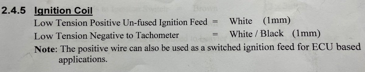
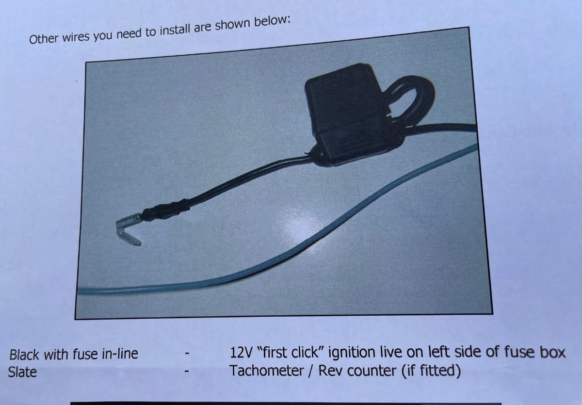
Another question! I have an Autosparks loom and a Trigger Wheel ECU loom. The loom instructions say “the positive coil feed can be used as switched ignition for ECU.” The TW loom instructions says one of the wires is “12v first click ignition” Do I need to connect these? (Sorry if it’s a silly question) I’ve attached pics… Thanks

-
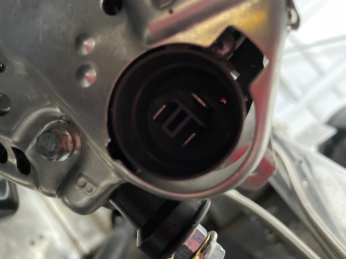
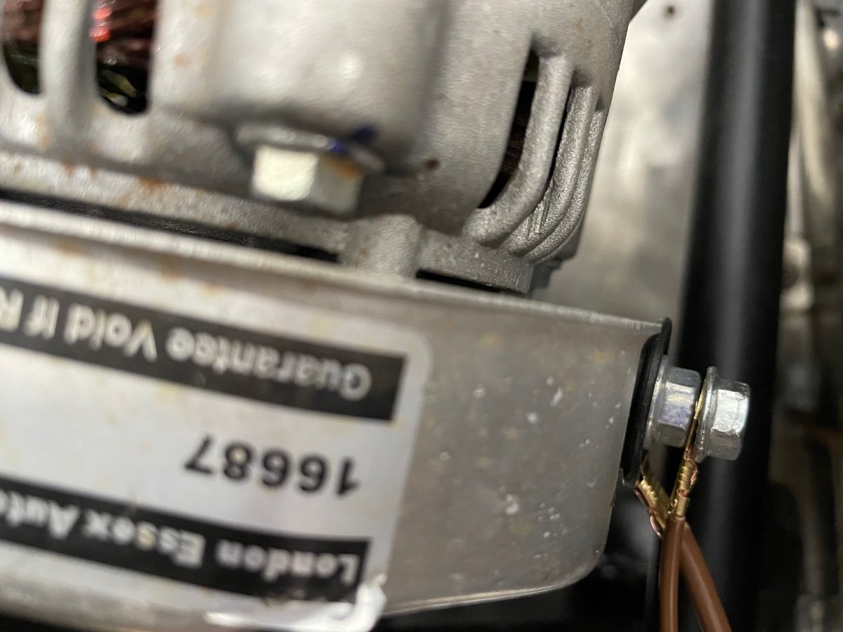
Question 2 I have a Zetec Silvertop, not sure what the alternator is off….possibly Escort It has a post for the positive leads but a three pin plug for the charger light. Is there any way (or process I can follow) to work out which pin I need? Thanks
-
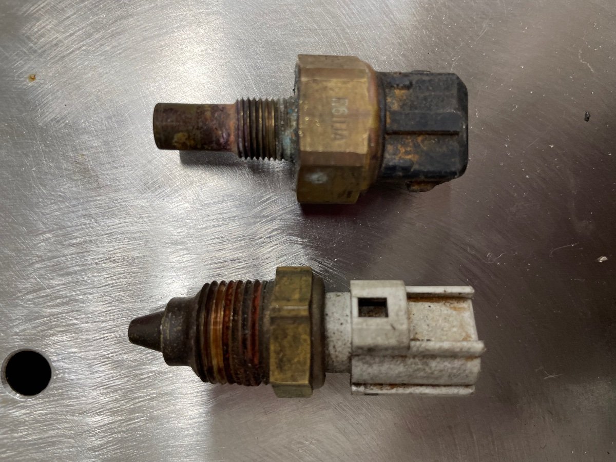
Thanks, I’ve got the aftermarket coolant rail and bike carbs on a custom inlet. Ideally I just need the temp gauge one to work as I’m going to have the coolant fan on a switch.
-
So, having started the electrics, here comes the first of many (I suspect) questions! The engine (Zetec Silvertop) has two sensors, does anyone know which is which - I assume one is gauge and one rad fan switch? Also, both have 2 pins but only one wire, so I assume one pin just goes to earth? Finally, do the sensors have a pos and neg or does it not matter? Thanks in advance
-
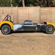
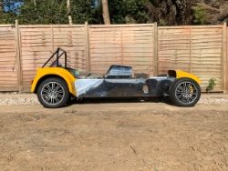
The fun starts here - anyone know this car?
Chris Scott replied to Chris Scott's topic in Build Threads
Thanks both, I’ve got some proper fabric loom tape coming to neaten up and protect further - will look into some tubing as well. It’s a brand new Autosparks loom, I’m no electrician so needed something that was plug and play(ish) - now I have a starting point I’m hoping it won’t be too bad to wire up! -
The fun starts here - anyone know this car?
Chris Scott replied to Chris Scott's topic in Build Threads
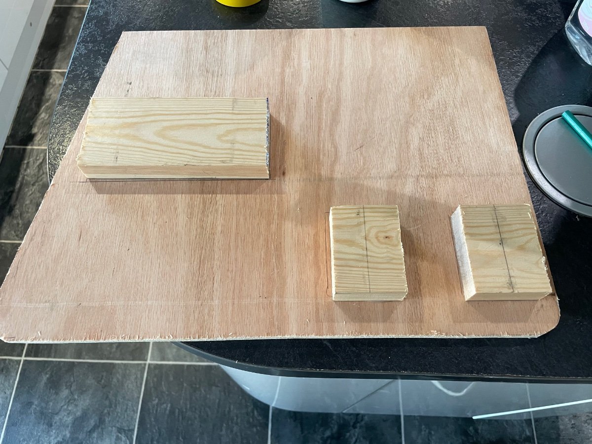
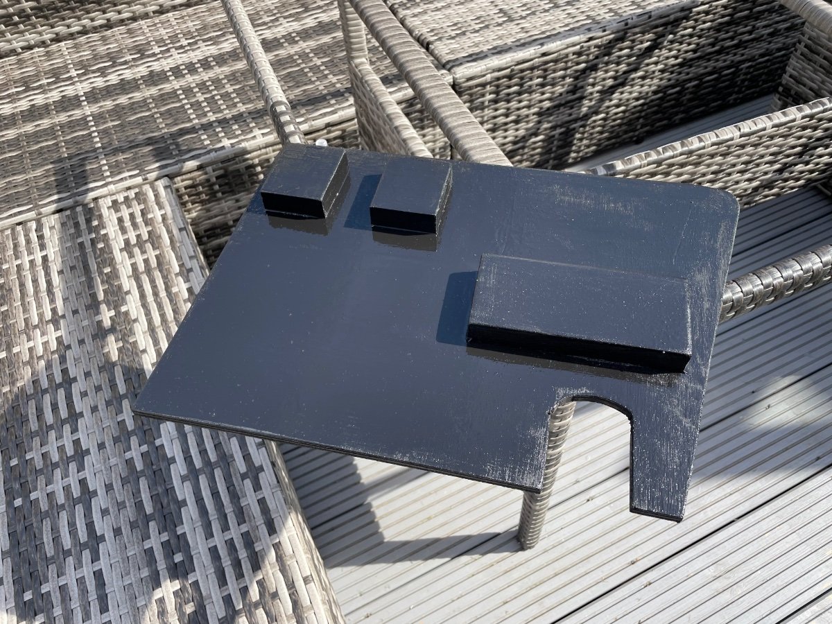
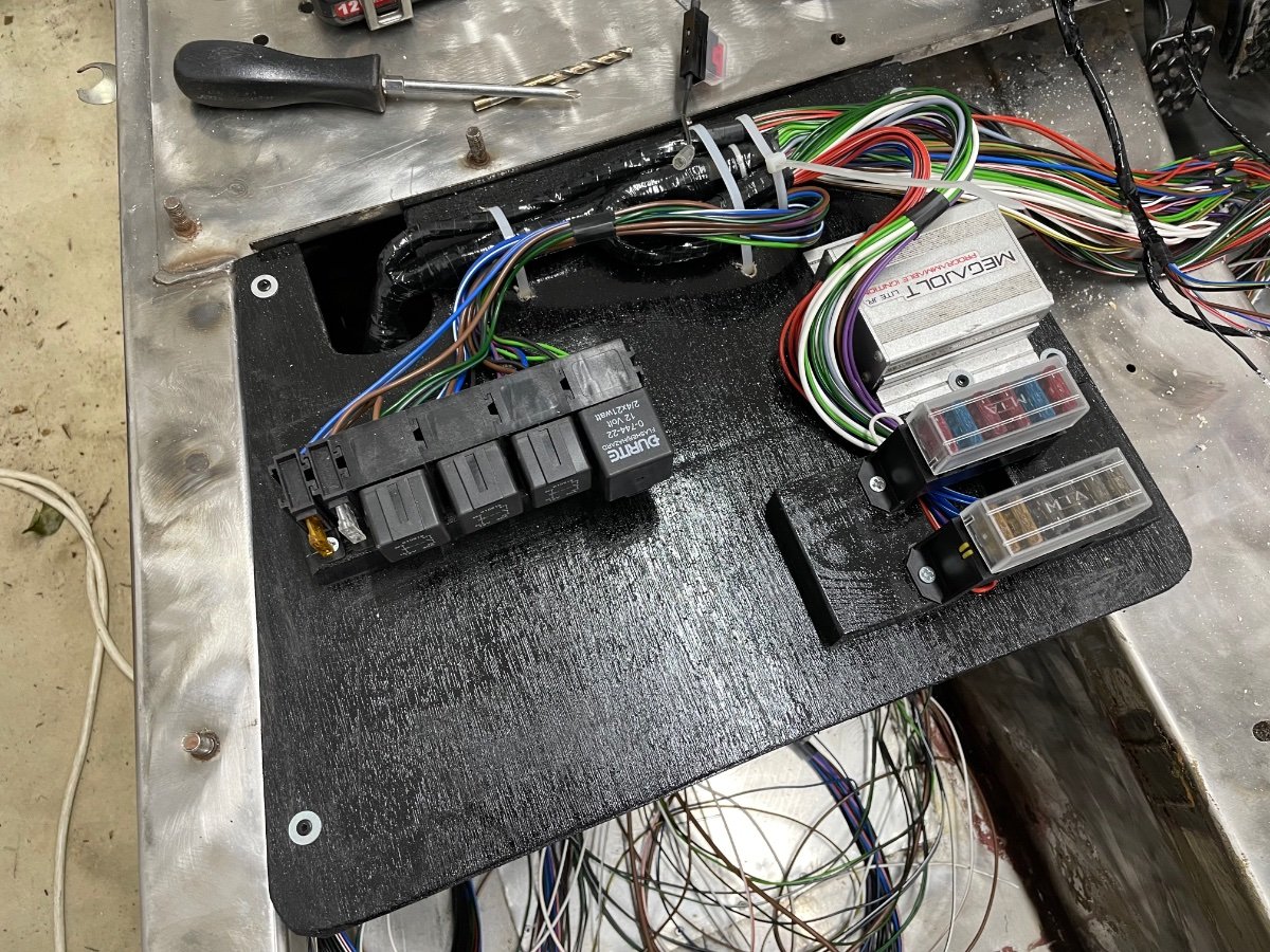
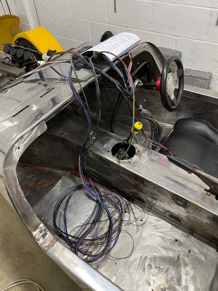
So after weeks of procrastinating (through fear of the task) I finally started on the electrics today. Having had several aborted attempts, I finally decided that the sensible path was to install the fuses and ecu first. I have built a small shelf to house the units (which sits above the passengers feet. I would love to have made it from metal but don’t have the tools or materials - but painted plywood looks good and should do the job.
-
that’s ok, I won’t hold it against you! I do think those double crimps look to be the way to go, and given the other advice it’s the best (and easiest) method for me. Thanks again, Chris
-
Will do, thanks
-
Do you happen to know the name of these type of connectors? as I think that’s exactly the way I’ll go.
-
Excellent, thank you. I’m wondering if it would be better to invest in a good crimper and quality plugs rather than a cheap soldering iron
-
Thank you for the insight, this is exactly my worry - I fear I’ll make a pigs ear of any method Will look into those connectors though as they look to be of a good quality/design
-
The fun starts here - anyone know this car?
Chris Scott replied to Chris Scott's topic in Build Threads
Thanks, yeah I’m worried!!! The look looks easy enough to install and connect - but I’ll have to make some kind of custom but for ecu etc and I’m just terrified -
The fun starts here - anyone know this car?
Chris Scott replied to Chris Scott's topic in Build Threads
Another milestone reached - now time to start installing the loom….terrifying but a big step towards getting it running!
-
Well, after a long journey I’m finally at the point where I need to install my new loom…and I’m terrified The good news is it’s a brand new Autosparks loom with simple to follow instructions - the bad news is electrics frighten me! I’ve just no experience! So the first silly question, what are the best connectors, I want simple but reliable. From what I can tell a lot of the engine bay will be eyelet, bullet and spade connectors - is it best to crimp these or solder? Any sets/kits of connectors people recommend? Thanks, Chris
-
The fun starts here - anyone know this car?
Chris Scott replied to Chris Scott's topic in Build Threads
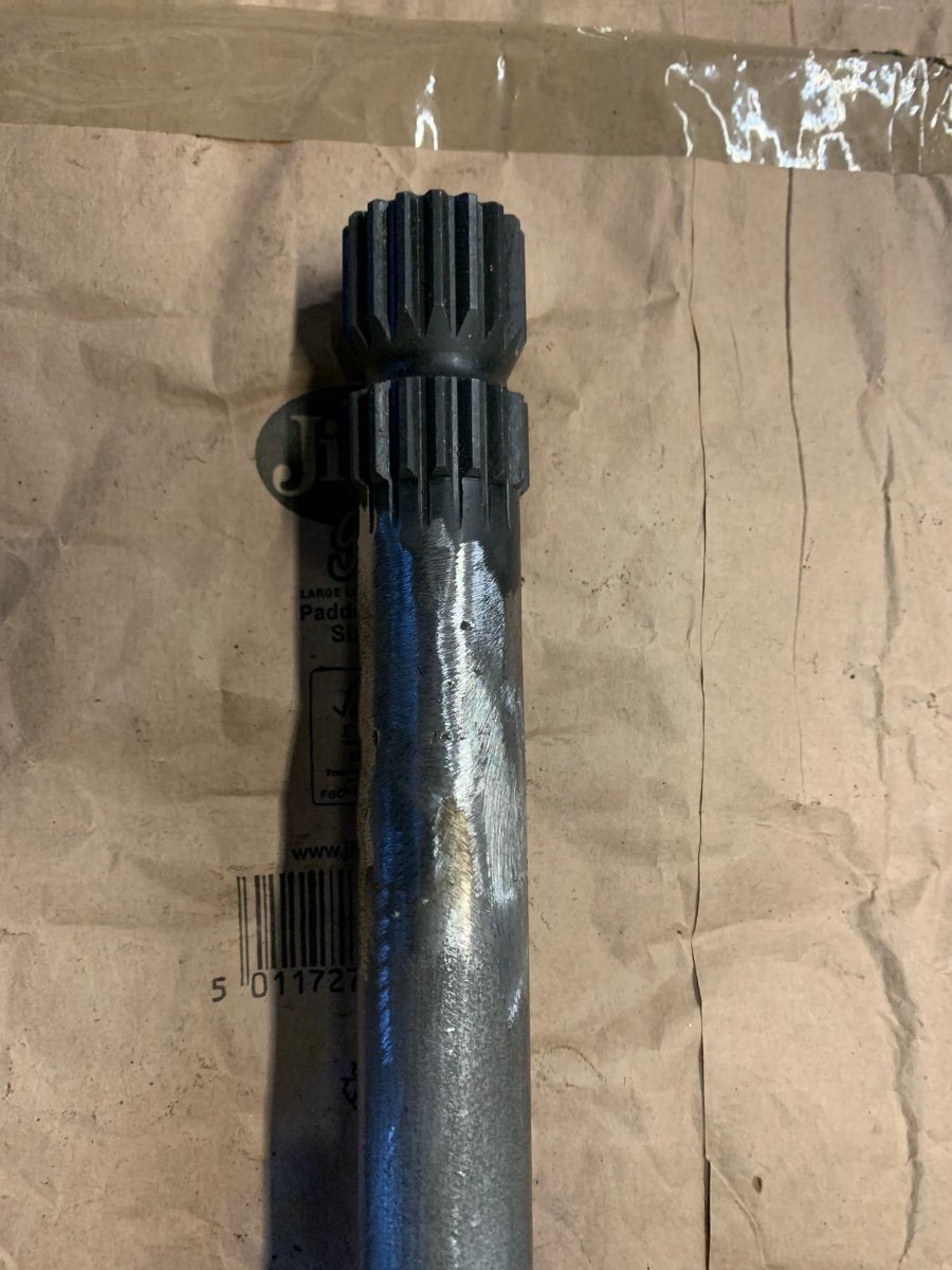
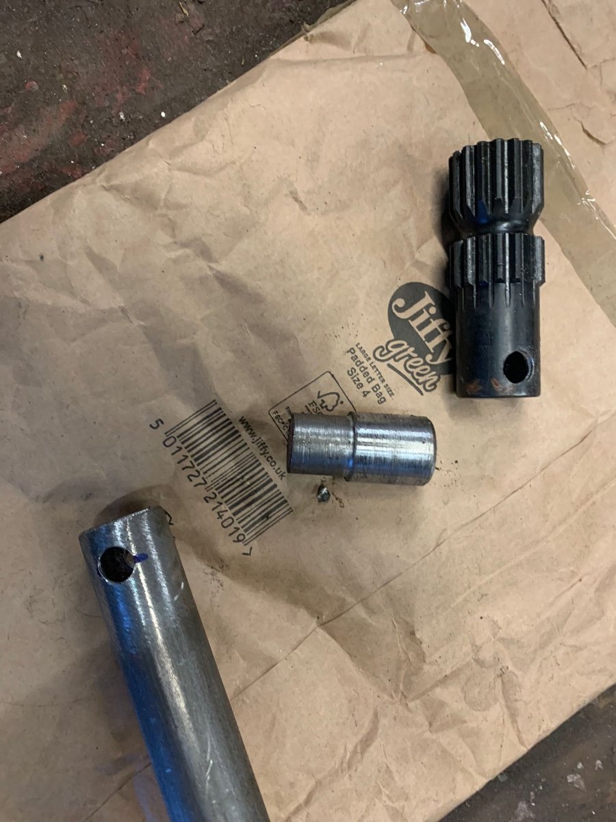
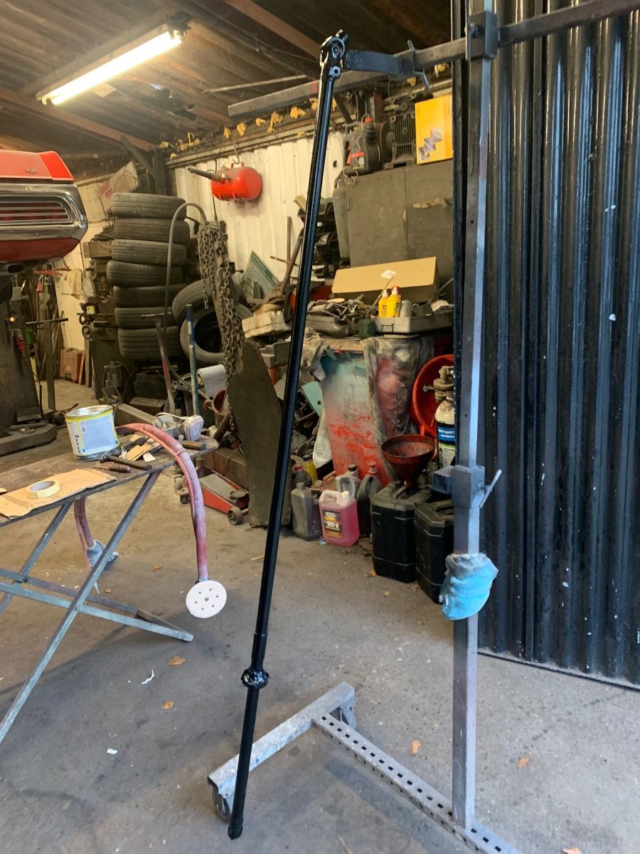
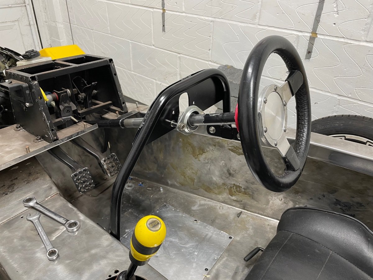
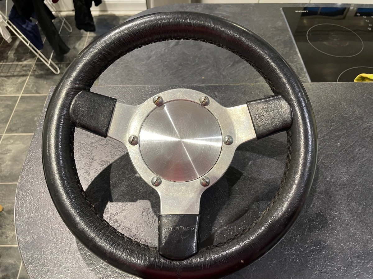
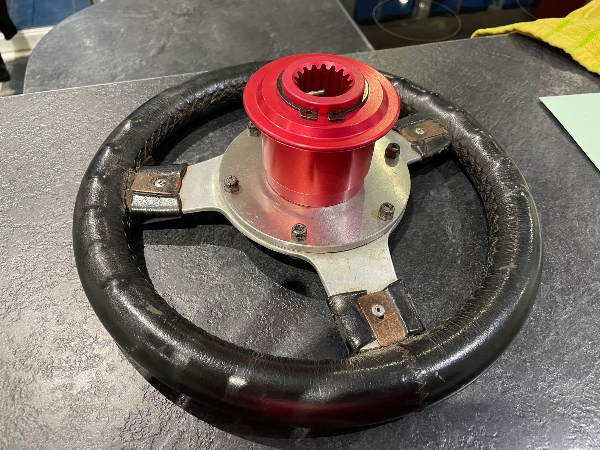
Column and mounting plate refurbished, new quick release wheel attached - a few more small jobs and then it’s time to tackle electrics
-
The fun starts here - anyone know this car?
Chris Scott replied to Chris Scott's topic in Build Threads
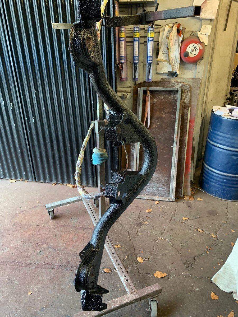
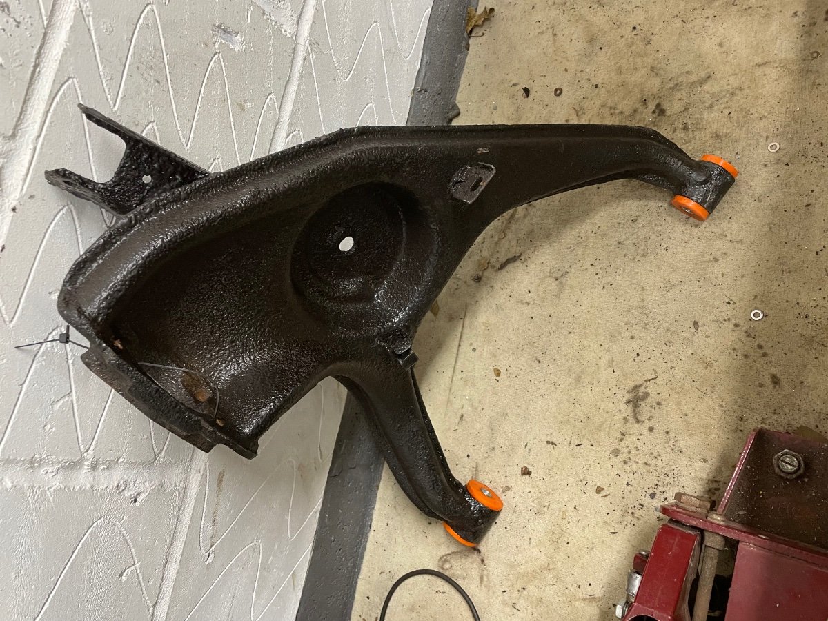
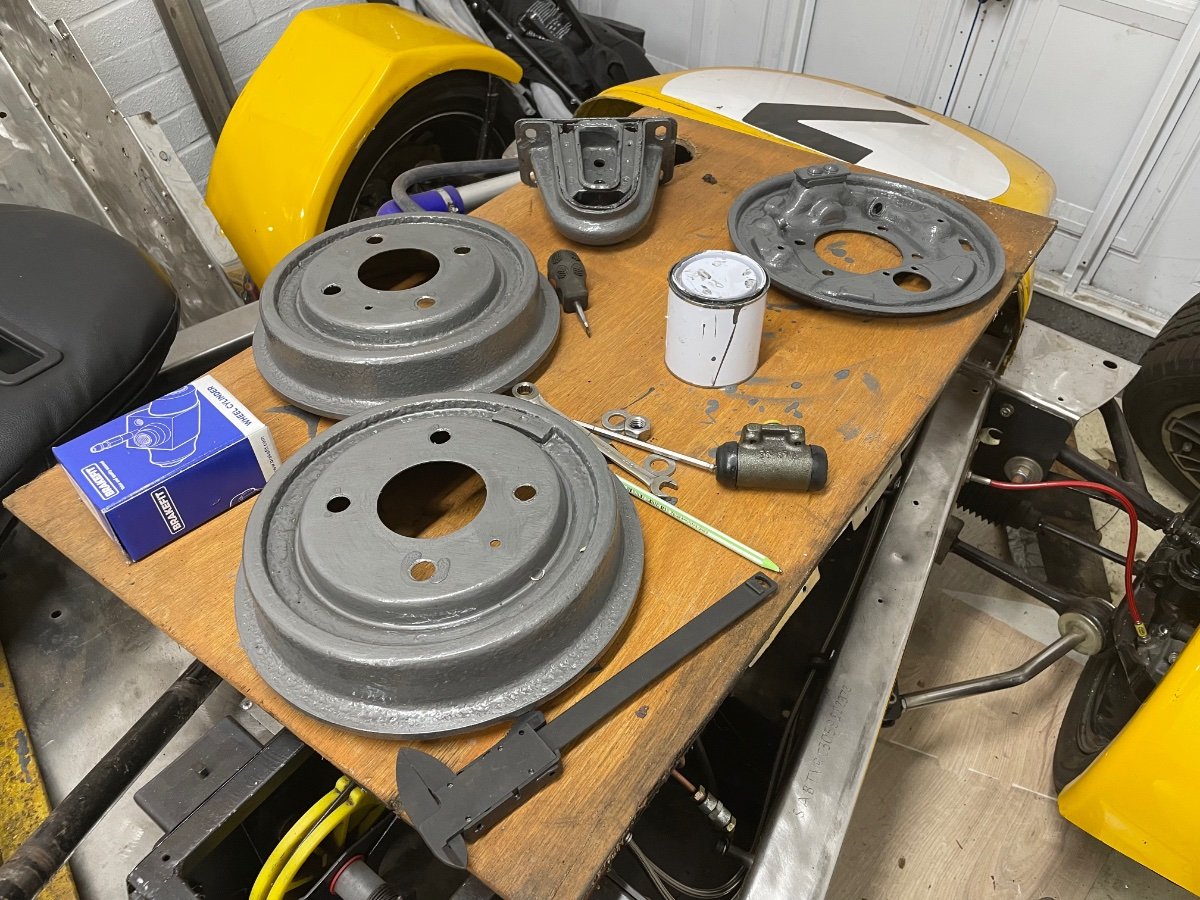
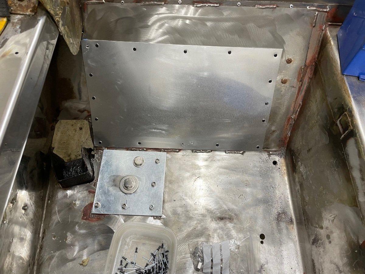
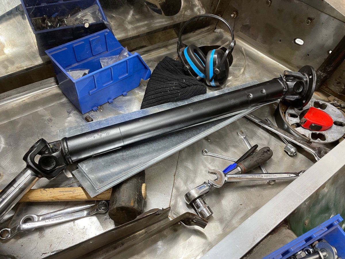
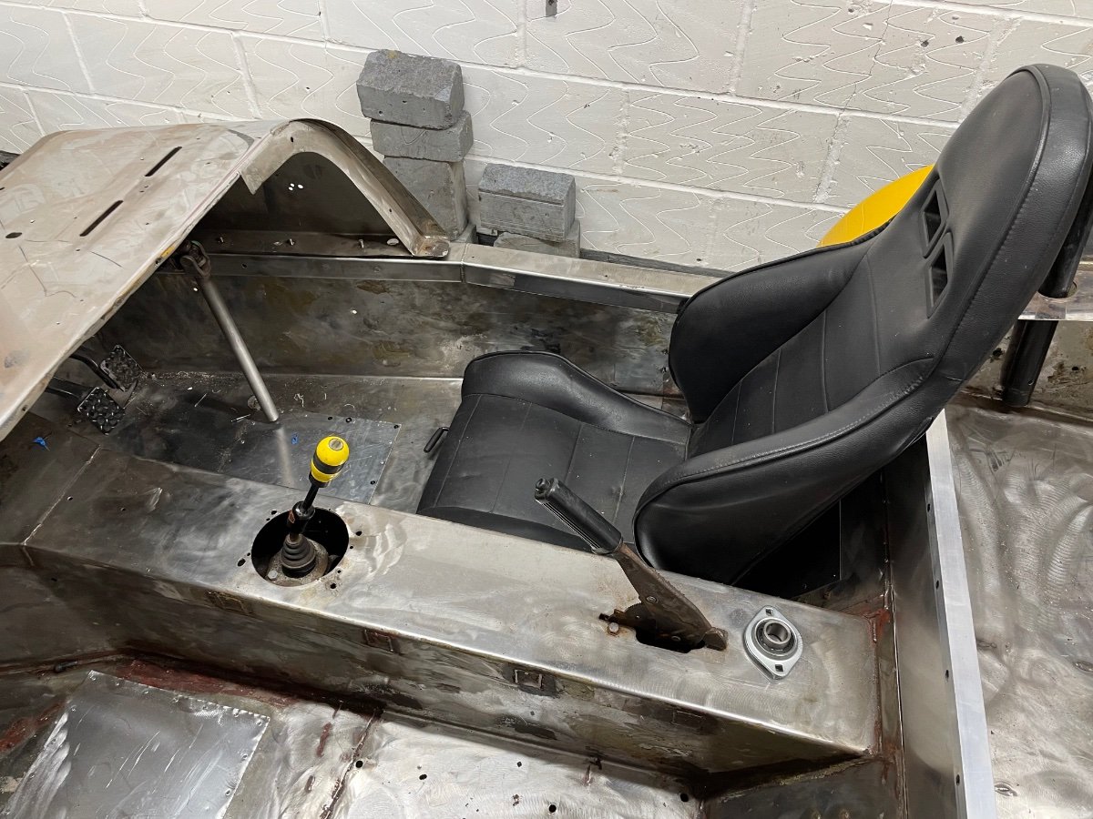
So…after a couple of months of forum inactivity I thought I would update the community on my progress…as there has been some! The diff has been freed from its prison of corrosion, cleaned, resealed and refitted into a refurbished subframe. New stainless bolts and poly bushes have seen that looking so much better! The backing plates and drums have been cleaned and painted and are now back on the car. I have replaced the mounting plates for the subframe for thicker galvanised versions as well as patched the rear bulkhead. The drivers seat is now fitted to new runners. Finally, a friend has machined me a lovely ally plate to mount the new quick release for my steering wheel. Next job will be mounting the steering column.
-
Thanks all, it’s all back together now - a pain to have the issues but a relief that it was only my carelessness not anything more serious!
-
Don’t be so sure I accounted for this I removed this morning and looks like it was nearly all my fault I will say that in my defence the strange thing is the shafts have the LH and RH threads the wrong way round (IMHO) as it would seem they would undo themselves as the car drove.
-
Evening all, weird one… I’ve had my hubs/driveshafts rebuilt (new bearings and gaiters) went to fit yesterday. RHS slid in and bolted up perfectly. Went to fit the LHS and it doesn’t fit, it slides into the diff, however the hub end is about 30mm away from the mounting point, it all binds up if I try to compress and bolt up. Any ideas? I assume maybe the CV has come apart inside or something?
-
Thanks all…as always
-
Now this interesting - because mine has an additional M12 bolt and the reinforcing plate - so maybe the other bolt is a little redundant. If that’s the case I’ll likely just go M12 for both
-
Evening all, does anyone know the dimensions of the big bolts that hold the rear subframe to the chassis? I thought they were M12 but when they arrived the shouldered part seems too narrow. I’ve measured the old bolts and it seems to be 12.4mm diameter so slightly bigger than M12, any ideas?
-
Thanks for the replies - sorry for my late reply. All sorted now luckily, just waiting on some parts then it’s time for the big reassemble
-
Thanks, it’s 100% one long bolt so either 6.5 or 7 - wonder if it’s my mistake as when I checked it says Sierra/Cosworth on my listing - would Cossie be different?