

Chris Scott
-
Posts
123 -
Joined
-
Last visited
-
Days Won
3
Content Type
Profiles
Forums
Events
Store
Community Map
Posts posted by Chris Scott
-
-
On 10/29/2022 at 11:43 AM, alanrichey said:
Airlock is a good suggestion. I actually got an airlock once that went to the top of the system, unfortunately that is where the water pump is located (Ridiculous Rover design) and it covered the pump so I lost all circulation and experienced similar symptoms to you. You need to figure out where the highest point is and try and bleed it. One trick is to jack up the front of the car so the top of the radiator is definately the highest point.
I have a feeling this is exactly what’s happened, the airlock is in/at the pump. Will Jack the front right up at the weekend

-
Thanks both, Alan, the switch is in the radiator - previously the radiator got hot, i then changed the switch as a precaution - obviously losing coolant in the process - I’ve topped it up and this is the first time it’s run since. Hence why I think it could be airlock.
Ian - yes I’ve seen about the water pumps - all I’ve read suggests I have right one - and it did seem to work before - but certainly something I will look at as well
-
17 minutes ago, alanrichey said:
No, that's correct. otherwise the light would be on permanently (and drain your battery). I haven't come across an alternator that gets a 12V direct from the ignition, but the bottom line is that the 'light' terminal is either not coming up to 14V or that wire between the terminal and the light is somehow permanatly earthed. If you remove the wire from that terminal I would expect the light to stay off when you switch the ignition on. If it comes on you have a short to earth somewhere along the wire. While it is off you can check what happens on the terminal. If it doesn't jump to 14V when you start the engine but the battery does go to 14V then there is an internal fault in the alternator.
Brilliant thanks - that gives me a few things to check
One day I’ll have a functioning car! 
-
4 minutes ago, alanrichey said:
When you turn on the ignition the warning light should have 12V on one side from the battery and the other side should be connected to the alternator at 0V, so it lights up. When you start the engine and the alternator kicks in then other both sides should go up to 14V so the light goes out. You would get these symptoms if the light wasn't properly connected to the alternator and was actually connected to earth instead. However, the current flowing through the light is used to actually excite the alternator into life, so that would indicate it is connected (unless you have a newer alternator that will self excite). Anyway, you need to check the wire from one side of the light to the alternator and find out why it isn't going up to 14V when the alternator kicks in.
Hi Alan, so this is my setup…
Alternator is a modern denso one, that gets a 12v signal from ignition to fire into life - this is all working now
The light is wired as per the generic loom instructions (which probably don’t take into account the smart alternator) which is 12v to one side from ignition* and then a wire to the “light” terminal on the alternator
however as it’s the ignition that fires the alternator and not the light I suspect i need to change something - just not sure what???
*the light currently has a switched 12v from the ignition circuit….should it be direct to battery instead?
-
Updated question - the alternator now appears to be functioning - I get 14v at the battery when running.
However the charge light on the dash doesn’t go out…stays red! As far as I can tell it’s all wired correctly…any ideas?
-
So, for every step of progress on my rebuild i seem to take two steps back!
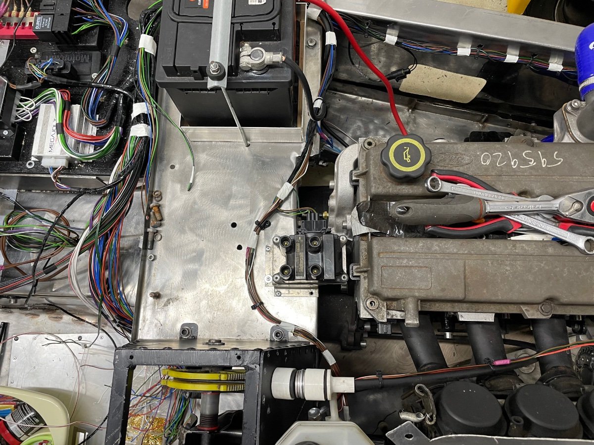
When my car (1.8 Zetec) runs the top radiator hose gets hot - I’m taking this to mean thermostat is working.
However the radiator itself stays cold and the rad fan doesn’t come on - despite the engine approaching 100
i cracked the rad cap and coolant started to come out so the level is correct and it’s pressurising.
Could this be as simple as airlock in the radiator? And if so any tips on how to cure it?
-
Started on the button yesterday, but still on three cylinders

Rev counter now works (bad earth), but alternator still doesn’t appear to be working!!! (Charge light doesn’t go out)
A bit of investigation has answered the 3 cylinder mystery…a bit wet!

-
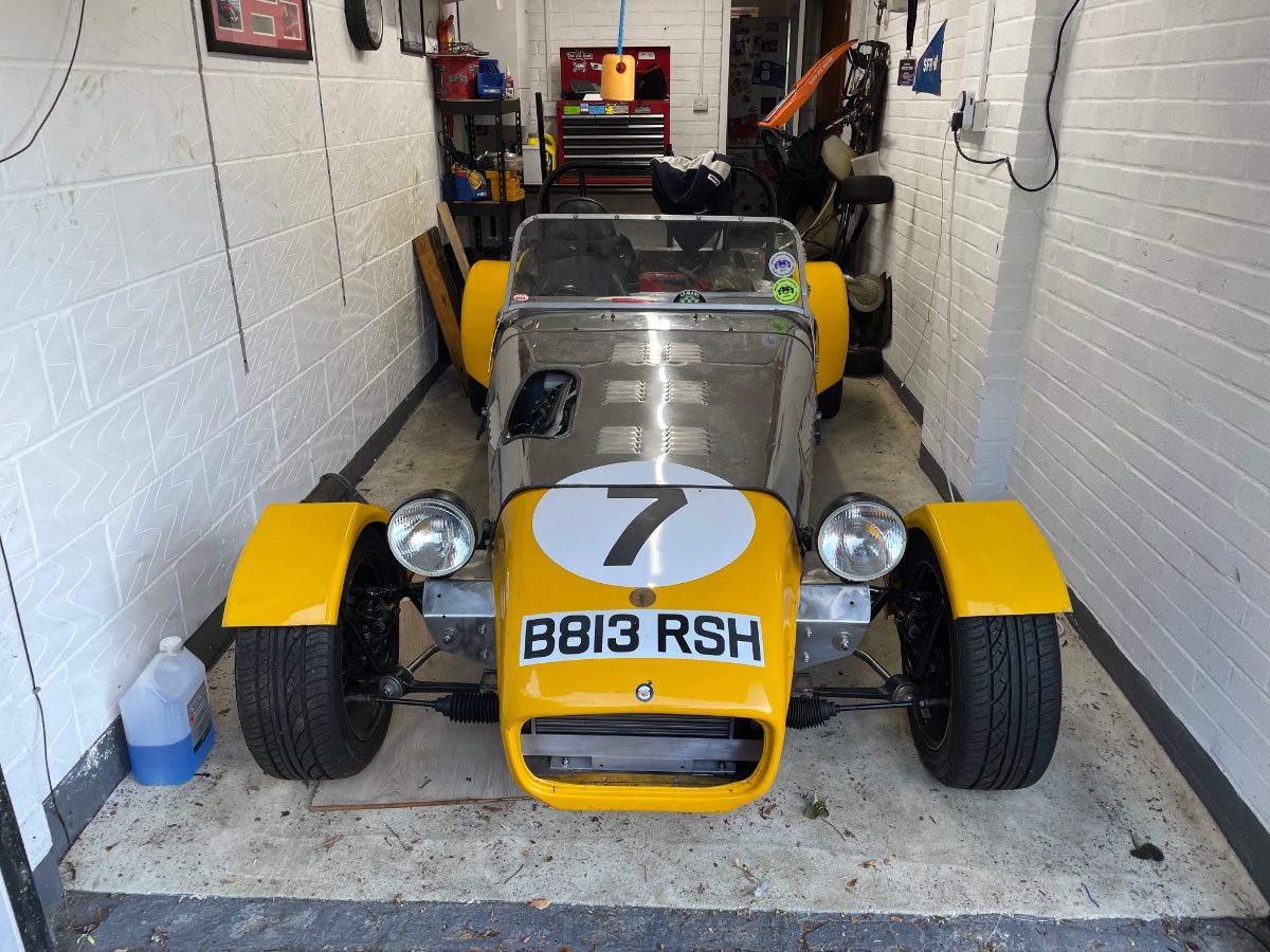
For the first time in two years, it looks like a car again!
Still a number of jobs to do but every one is a step closer!
-
Bit of cosmetic work today!
-
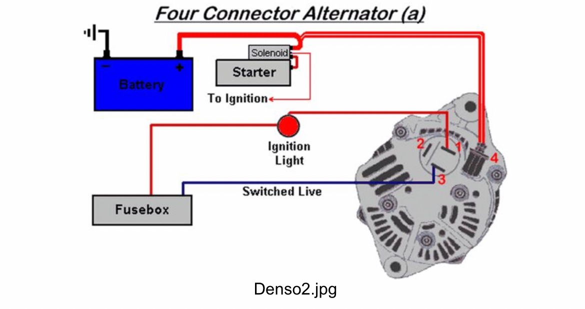
I’ve done some more digging, based on what’s been said on here and I think I have a 4 wire alternator like the picture.
I have a 6mm and a 2mm wire for the alternator (both going to battery) and both attached to post on alternator(4).
I have a warning light wire too(1) - so 3 wires only.
I don’t have a switched live going to the alternator at all, do you think this could be the issue?
-
6 hours ago, IanS said:
A couple of thoughts.
The 6mm one carries the main charging current which would be the IG and should go to the battery.
The 2mm one on a type 2 would also go to the IG connection OR on a type 3 would go to the S connection. Safe says leave open for now.
1mm to the warning light. The other terminal of the warning light goes to switched live.
Then do not forget the 4th wire. Every electrical circuit requires a conplete circuit so the battery negative needs connecting to the alternator body this is the 4th connection, it is normaly achieved by the mounting bolts of the alternator to the engine block and hence back through the starter earth strap to the battery.
So if the warning light is wired wrong the alternator will not start charging as some current through the warning light is often used to boot start the alternator.
OR painting the alternator brackets thus preventing the negative connection so no charge, on older alternators this used to fry the control electronics in the alternator, most modern ones live through this but any form of arc mig tig welding with the alternator connected can still fry the alternator.
If you have a volt meter measure the battery terminal voltage just before starting and then with engine revs above 3000 rpm if the voltage rises then the alternator is trying to charge, if not there is a problem in charging.
I hope that this helps
Very helpful thanks! Both the block and bracket are painted so well worth looking at the earthing, I’ll also give the voltmeter check a go when revving.
-
Hi all, I need some help!
Car now runs, however the alternator is not charging the battery - I have no idea if it worked before tear down, so fighting blind…especially as I’ve rewired the car too.
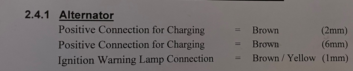
The wiring loom has two positive wires to the alternator, a 6mm (main charge) and a 2mm called ‘positive connection for charging’. Currently I have them both to the +ve post on the alternator but it’s not charging.Have I wired it right or wrong? Could the 2mm be a “battery sense” wire and need to go to the regulator? Could that be why it’s not charging?
It’s a Zetec Silvertop. I’ve included the wiring guide and a diagram of the alternator plug (type 2 or 3)
-
Time for another update - although not quite as positive as I hoped.
Fired up again yesterday and now running nicely on 4 cylinders. However there are some problems!
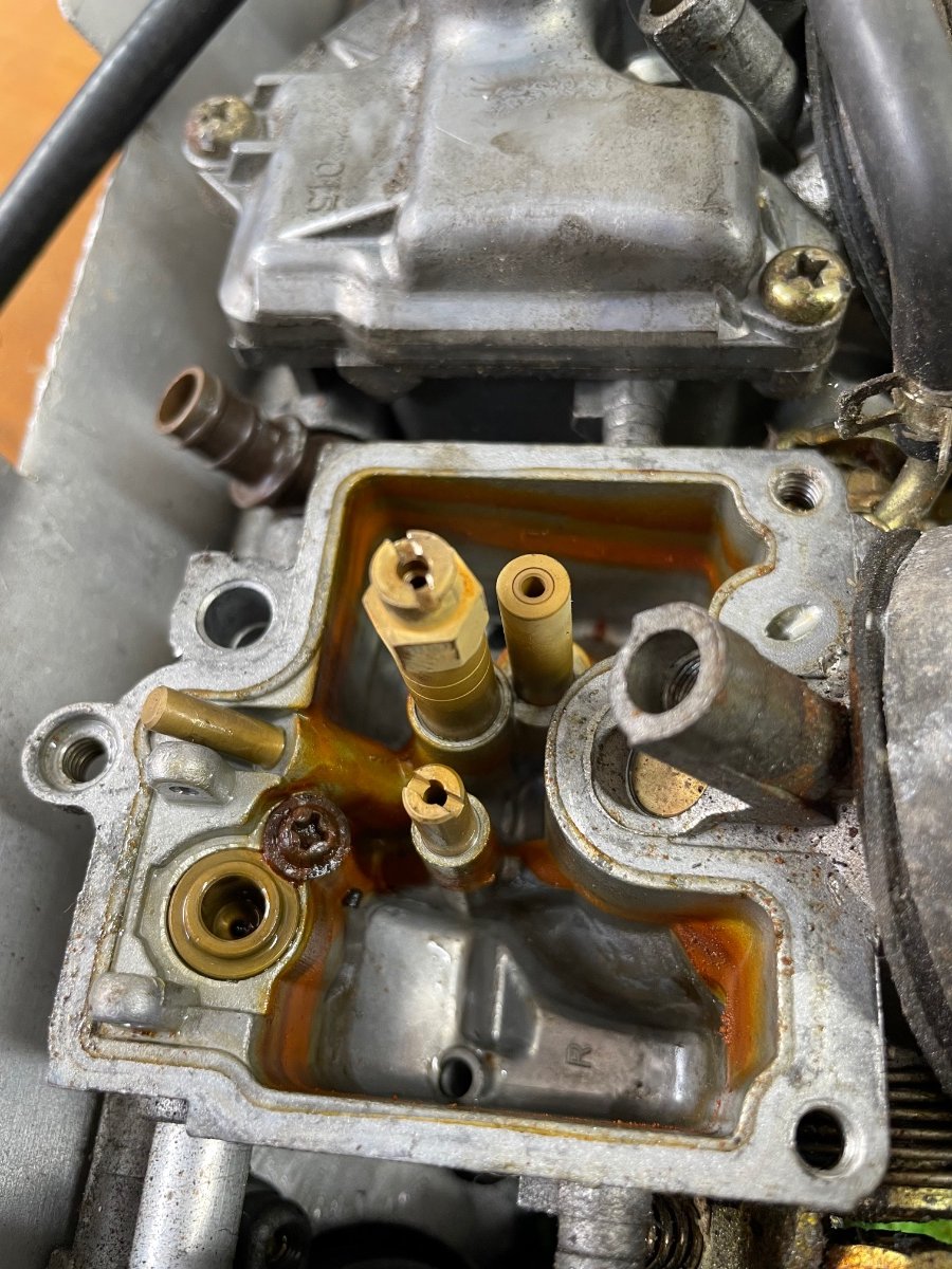
Couple of fairly significant oil leaks, hoping it’s just from the old rocker cover gasket (new one to be fitted when I paint the cover). A coolant leak which is hopefully the lower hose. An alternator that’s not charging - probably needs new as it was damp stored for years before I got it so could well be past saving. Coolant switch didn’t seem to work - need to remove it and test it with some boiling water as it’s brand new.
Finally the rev counter didn’t work (assuming it’s wired correctly) is there a way to test whether it’s the rev counter that’s at fault?
-
Again, been a while!
Today was a big big day….despite only running on 3 (issue is plug lead), we have a running car!
This is a big moment! First time it’s run since the day we bought it.
-
 1
1
-
-
On 7/16/2022 at 3:29 PM, Sparepart said:
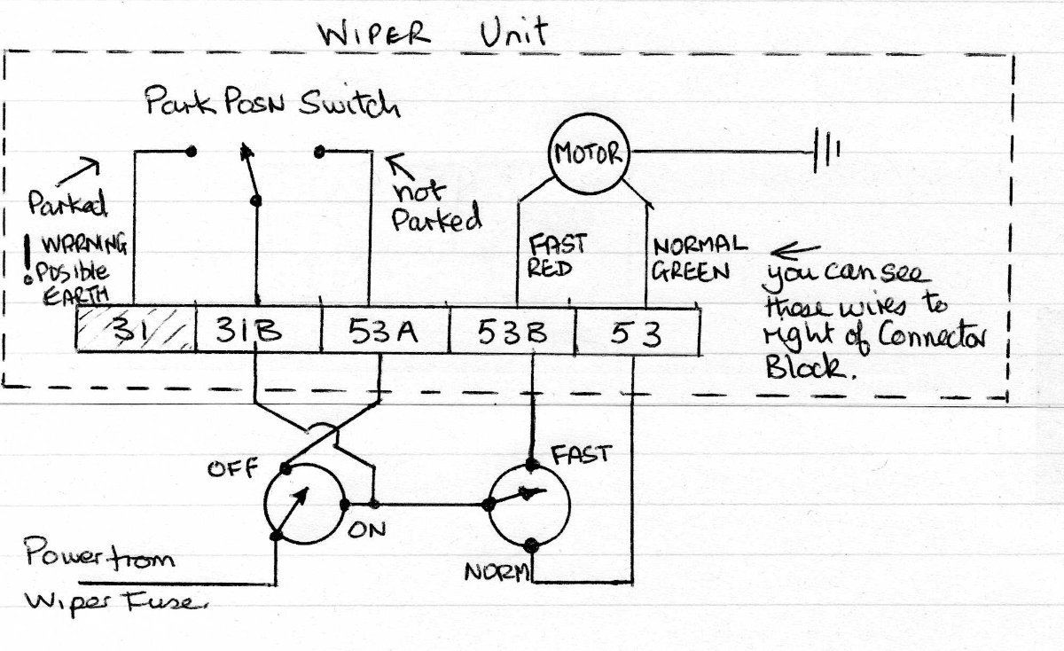
Okay, I have had a good poke around with the meter probes, and can confirm that connector 31 (leftmost in the photo) is connected to the motor body and the whole wiper mechanism. So the motor won't run without the body being earthed which means connecting connector 31 to earth. This means the my brilliant circuit diagram above is useless because it will cause the fuse to blow when the wipers are turned on from the park position. So I have given the matter more thought and have come up with a circuit that should work, using a relay. It still uses the two two pole switches, however could easily be modified to use a 3 position switch, where each position would give a connection. Anyway I have inserted the suggested circuit below. I realise you don't intend to use it, but I just couldn't leave this thread with a duff circuit diagram.

Sorry for the late reply, this was so helpful!!!
Now have a fully functioning wiper circuit
-
11 hours ago, Sparepart said:
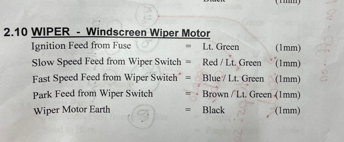
Yes a simple switch from a suitably fused power source to 53 or 53B will give normal or fast motor speed. In it's original mounting in the Sierra the wiper motor and mechanism is fixed via rubber bushes to absorb vibrations, so if you have retained these the outside case of the motor will not be earthed. The contact 31 needs to be connected to an earth point. That would be the black wire in the wire list you posted at the start of this thread. Obviously if you use a simple switch the wipers will stop wherever they are turned off.
Absolutely ace, thanks! I will use your diagram to have one final bash as I may have wired it wrong! But if not I’ll do the simple circuit described above
-
1 hour ago, Sparepart said:
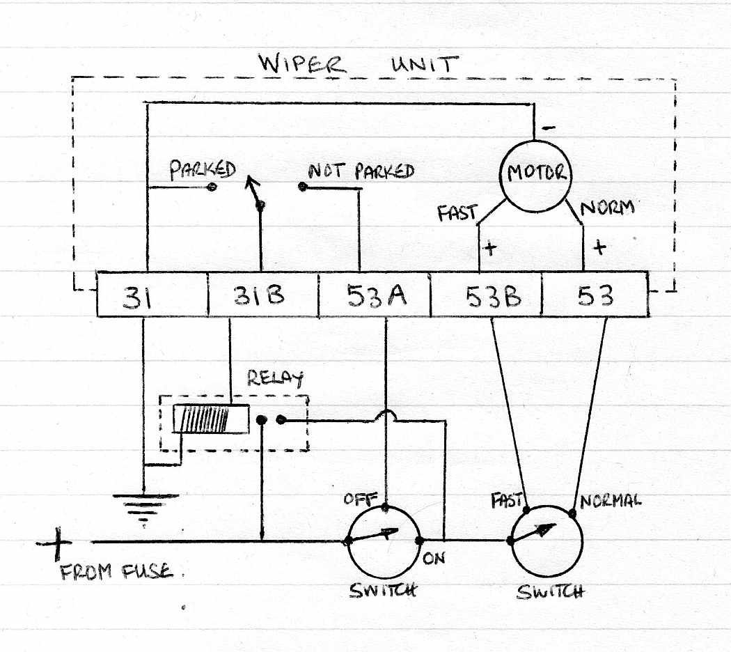
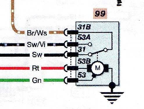
I am part way through wiring up my Sierra wiper motor, but have not finished yet due to other distractions, however I can share my plan if it helps. Firstly I include a snippet from the wiring diagram as fitted by Ford.
This shows the original wire colours (Sw = black, German I think) The important thing is that as the motor turns it operates a switch that connects 31B to either 31 (parked) or 53A (not parked) I worked this out by monitoring the switch connections when the motor was turning. By the way avaoid trying to power the motor by connecting 53B and 53 to the battery, the motor runs very fast, too fast like this and would burn out.
I now include my planned circuit, using two independent 2 pole switches to allow wiper self parking and two speed operation.
The numbers on the connection block are in the same order as shown on your photo. Note I believe that connector 31 is earthed within the motor assembly so you must not wire any power directly to 31B because if you do a short circuit will occur when the motor arrives at the park position and the fuse will blow. This might be what is happening in your current wire setup. In the above the wipers operate via two switches, a "master switch" turns the wipers on or off which a second switch selects the speed. When the wipers are turned off and not already parked power from the Off pole on the switch is routed through the Park Position switch to turn the motor until it reaches the park position, and there disconnect. I repeat that I have not yet built this circuit, it's just what I plan to do if I get problems with the column switch and delay relay etc in the fuse box.
This is really helpful thanks, but my limited knowledge of electrics still sees me stuck…but hope you can help…
If I wanted to run a simple on/off switch to make this work on (let’s say) fast setting only - would I just need a switch between the feed from the ignition and the 53B terminal?
Am I right in assuming the motor earths through the body and not any of the terminals? -
Essentially, from my limited knowledge, I believe the parking circuit is causing me the grief…just not sure how to cure the issue
-
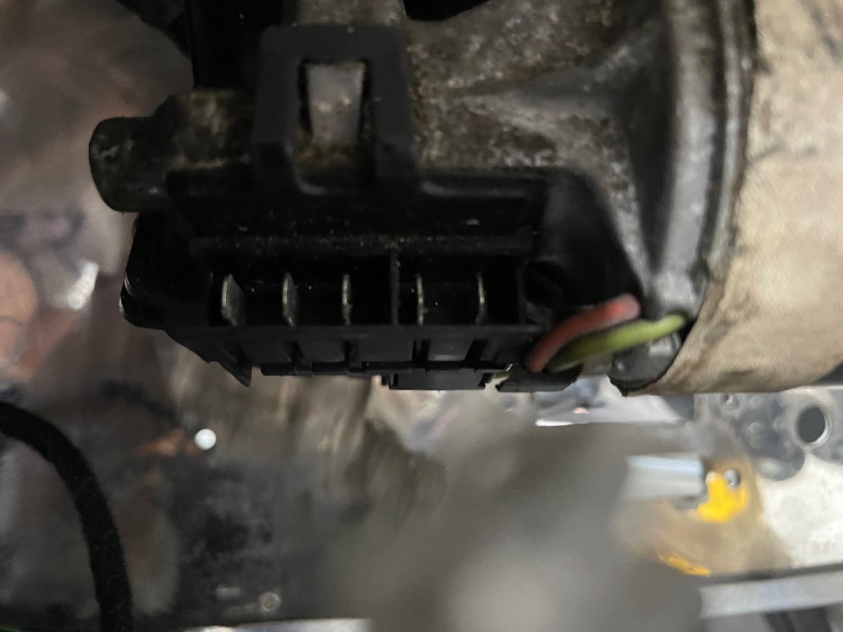
Hi all, this is a bit complicated to explain but here goes…
I have a Sierra wiper motor, but doing away with Sierra column switches.
When I switch ignition on the wiper motor makes a grinding noise and blows it’s fuse.
If I wire directly to battery the motor is fine.
My question is, if I want just a simple on/off for wiper motor how do I wire it?
As loom has 5 wires and the feed from fuse is a permanent live…I assume the old column switch did some magic as you normally select a speed.
-
1 minute ago, shaun_tomo88 said:
Very lucky man
Honestly - it really frightened me…I’m always very health and safety conscious…one lapse and Christ did i nearly pay for it! I’ve put the grinder away in the shed - never liked it and always scared of it!
-
Update 2 is more akin to normality.
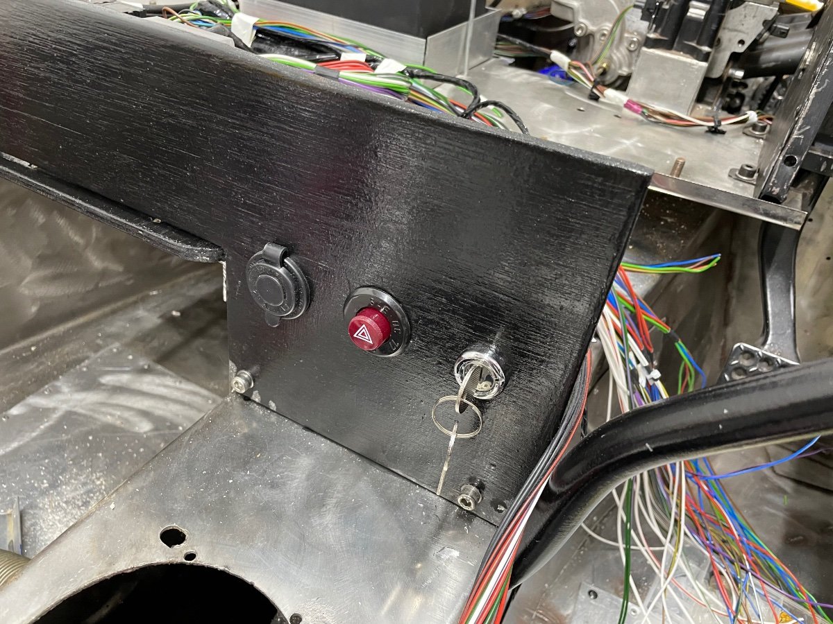
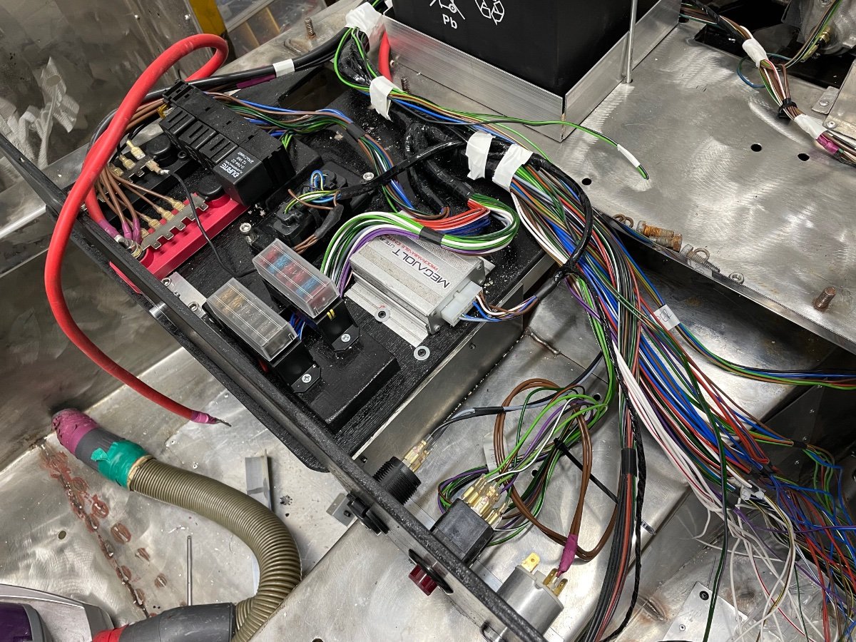
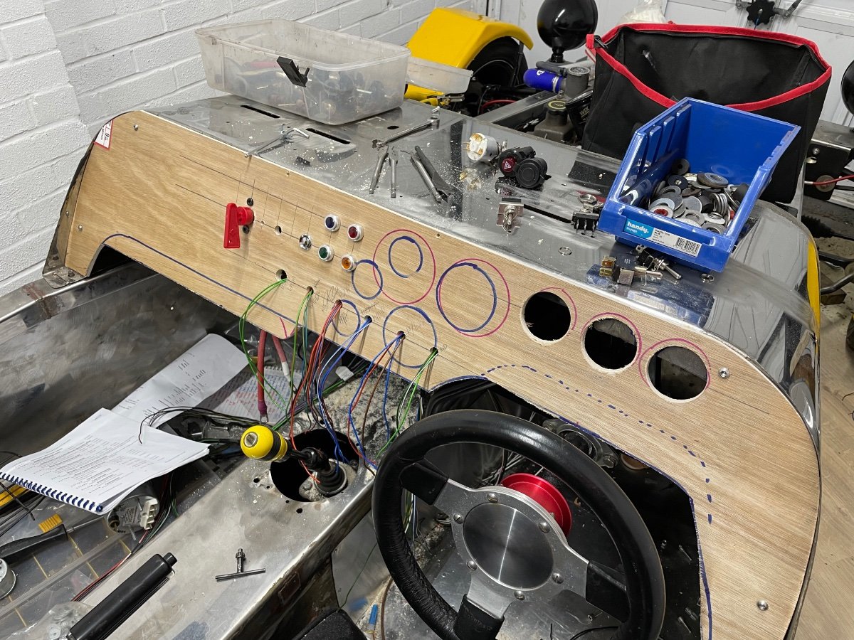
Progress on the loom is excellent, I’ve built a lower dash for the hazard switch, ignition barrel and 12v socket. I’ve also built a new main dash which is on its way to being wired in.
Initially I will paint the plywood black - then once the car proves it’s a runner I’ll cover in faux suede.
-
So…a couple of updates since I last posted…
Number 1 is semi-serious as I came close to never posting again.
4 days ago, and a couple of days after the birth of my 2nd child, I decided to quickly do some work on the car.
After cutting a hole in the bulkhead I decided to use the grinder to smooth off the edges. As it was a tricky area I had to remove the guard (mistake 1), I also had shorts on (mistake 2). On the last pass with the grinder the disc grabbed, the jarring motion sent it into my leg, across my groin and jamming into my stomach!
I walked off the pain, relived no one had seen my idiocy - when I looked down I saw the 5inch long, 1 inch gash in my leg!
6 hours in A and E resulted in the removal of part of the disc, stitches and a lesson learned - genuinely…6 inches higher and I may not be here to tell the tale!
-
1 hour ago, nelmo said:
Well, wherever your earth is - my dash gauges all have a common earth wire which presumably eventually goes to the chassis earth.
Thanks @nelmo - and for all the help so far! Hopefully nearly there with main electrics - then I’ll need to make an exhaust before starting it
-
So sorry; the electrical questions are coming thick and fast!
Just ordered a sensor for my temp gauge which has one terminal (it earths through the body) however my loom has a wire for earth to the gauge.
Do I just earth to the chassis instead? I assume so…

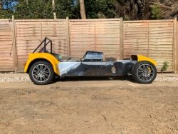
The fun starts here - anyone know this car?
in Build Threads
Posted
So…it’s been a long cold inactive winter.
With a heavy(ish) heart I’ve sold the car/project.
I’ve enjoyed it immensely but sadly a new job, new house and new baby have meant that it’s just not going to get the attention it deserves. I need the space and time!
The good news is it’s been sold to a classic car enthusiast who plans to restore it fully and take it to Le Mans, which is great because it had been before! I am confident he’ll carry on my work and get it finished.
I just want to finish by saying a massive thank you to this community, I have never ever met a group so helpful!
Thanks for everything, all the best.
Chris