


knights_templar
-
Posts
1,215 -
Joined
-
Last visited
-
Days Won
5
Content Type
Profiles
Forums
Events
Store
Community Map
Posts posted by knights_templar
-
-
no, defiantly not.
consider pin three as the ECU's way of switching everything, related to itself, ON.
Switch on the ignition and pin 1 goes live, this feeds everything NOT associated with the ECU system, that needs a live feed, Alternator field terminal for example, and ECU power.
On getting a live feed, the Emerald ECU switches pin 3 to ground.
I have no idea which way around your Mazda ECU switches it, normally ECU's use ground switching, but I do know that one of the ECU's on the MX5, live switched the coil packs, you have to mess with the Emerald settings to get these to work, so it's possible it could live switch other things as well.
One of the reasons an aftermarket ECU, Emerald is one of many, is preferred over the original.
With Pin 3 to ground, ignition on, Pin 2 goes live, feed from the ECU relay, see fuse board diagram.
Pin 2 is the power for the ECU stuff such as Lambda and Coil packs.
Check your donas wiring diagrams, as I say some coil packs are live switched, cant remember which age range of MX5.
I hope this makes sense.
Regards
Simon
-
This is from memory, and that is fading due to age.
Please note that the main loom was designed to be used with an engine/ECU sub loom, and Emerald ECU.
As you mention the MX5 ECU I assume you are using that, and making your own engine loom.
I do not know if the MX5 ECU switches the same way, you will have to investigate.
Loom plug
Pin 1, ignition switch live, 12V+ when ignition is turned on.
Pin 2, is 12V + from the main ignition relay pin 87, but only when Pin 3 is grounded
Pin 3, the ECU grounds this pin, which switches on the main relay pin 86
So, switch on ignition and Pin 1 gives 12V +, this wakes the ECU, which grounds pin three, which in turn, switches on the main fuse board relay, which makes pin 2 go 12V + for engine components.
I hope that makes sense.
You can easily check with a test light, and a bit of wire to ground Pin 3, you can also check Pins 4 cooling fans and 5 fuel pump/pumps relay by grounding them.
Note when pin 4 is to ground Pin 12 goes 12v+ to feed the high pressure fuel pump
-
You will need to discover where the play is.
The gearshift lever pivot (rose joint type ball) should be fine, but it screws into the end of the shaft coming back from the box mounts, they have come loose.
The fork joint at the bottom of the gearshift, where it attaches to the operating rod can open up if the bolt has been left to loose.
The coupling at the end of the opp rod where it attaches to the gear box shaft has also developed play in the past.
From memory it's a Ford coupling, but the pins can wear, although if there is movement in the coupling check the hole through the Opp rod for going oval.
-
Sorry lost track of this one.
With Blue, all the gauges need a + and a -, indicators need the same but only at the rely, usually behind the dash.
Common denominator is the dash + and -, usual one point on the loom to dash
-
interesting diagram on the blog, still can't make head nor tail of it

-
do you want the emissions map?
but be warned, it is still a fiddle.
MOT does not test the same way as IVA, so you will still need your lap top
-
Main loom and some of the adaptor plug in looms, were designed and built by a guy called Brenden.
Things change, so it is possible they don't use it now, but both the Mk1 and Mk2 looms had the start button provision.
Could be the person you spoke to was not conversant with earlier loom.
-
you will have, the Ford system does not work without it
-
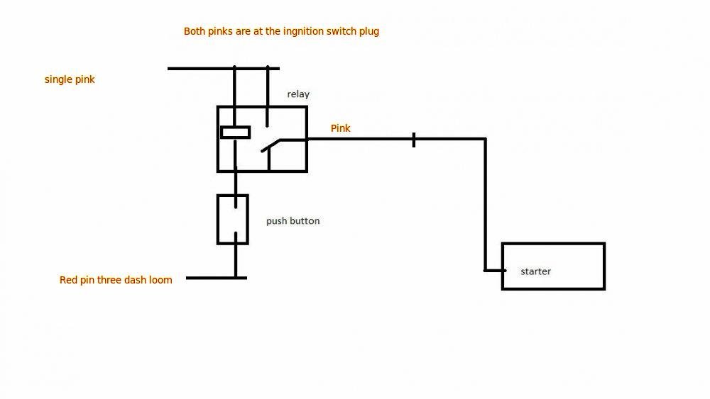
Quick look at IanS diagram, can't think of another way off hand,
From memory you have a GBS plug and play on a Ford donor
I have put in the connections I believe will work with that setup, alternator light is taken care of in loom, bridge into dash plug don't cut
If you are using the savage switches you can make the switch illumination work as the alternator light, or with the alternator light, just need to add a links to the back of the switch.
can add those if you wish
I should add this is not tested but I think the worse that can happen is that fuse 1 blows

-
In my experience people just over think it.
There is no need to know how it works, just how to test why it dose not.
Martin has a problem, what does he check first?
The clue is actually in the problem.
"gauges and indicators not working"
Any one?
-
Test paramours are set by the vehicle registration details.
Age related is the age of the engine at IVA, if not known, it would be set at the standards of the time.
Zetec engine for IVA will be
Tick-over
CO < 0.30
HC < 2002500 – 3000 RPM
CO < 0.20
HC < 200
Lambda 0.997 – 1.030For MOT it will be the same settings, but the test procedure, in the MOT emission tester software starts the test countdown at anything above 2500, it does not have the upper rpm, see previous for problem with that.
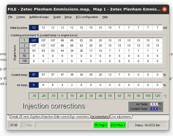
IanS is correct ECU temp should be reading similar to water temp or it will over fuel.
As mentioned before, my stuff may be out of date, but the original Zetec plenum map switched off fuel enrichment at 70 deg C, But there is air temp enrichment, so you will need to check that as well anything above 20 deg C is OK.
I assume you are using the Ford throttle body? which is often the culprit for it being that far out using the map details attached, the throttle butterfly is not flat so air flow through it is not progressive, and not helped by having to fit a throttle idle screw.
Have you matched the map to the throttle ?

-
The early GBS exhaust had the CAT in front of the silencer, looked like a snake that had swallowed a rabbit.
Latter exhaust had the CAT in the front of the tube, bracket also changed around the same time from bobbin to the hook type, but there are a number of versions
The GBS IVA map is a base, starting point, it is close, but only if the throttle and start of the map are matched, a simple procedure, but I found rarely done.
Matched correctly the IVA map I used would generally fall in at idle, and will get very close at the fast run, however IVA emission is tested between 2500 and 3000 rpm.
The map starts to go lean at 2500 rpm, getting leaner toward 3000 rpm, you can change the mixture by careful adjustment of the throttle position whilst the test is carried out, but at 3000 it goes full rich again.
MOT just says rev above 2500 rpm, and I always had troubles with MOT, unless allowed to control the throttle. It's a fiddle as there is a delay between throttle and reaction on the tester.
Wide band lambda is the best way, but again in the map I know, will need switching on, and calibrating in software, the map then needs the target set.
It will have no effect on tick over, as someone said above, none will work there, again it's a case of matching map to throttles, which should make it fall in, after that, manually tweaking as required.
Fast idle will be controlled by Lambda. But it will only be good for the test, as from memory, and it is failing due to age, auxiliary fuelling is not mapped in the IVA map.
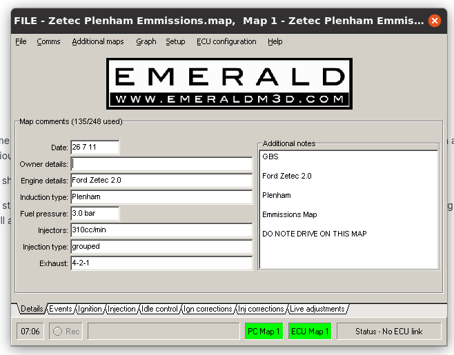
My info may be a little out of date now, but the IVA maps I know, and still have somewhere, were built for the three throttle bodies/induction systems that GBS were doing at the time, Jenvey, AT and Plenum. I do not know if maps were done for other options.
Best maps are those built specific for a vehicles setup, on a good rolling road, by someone who knows the ECU, and with Emerald I would get one for Emissions and one for Power, and have a map switch.
IVA and power maps I know are dated 26th July 2011, you can check with the software, but I am sure there are other versions out there, so approach above with care, but always match map to throttle unless it's built for your car.
-
what bit do you need the screws for?
-
We need more info
Which lambda, narrow or wide band?
-
If the donor is Ford try the alternator mounting brackets are earthed
-
Found It
-
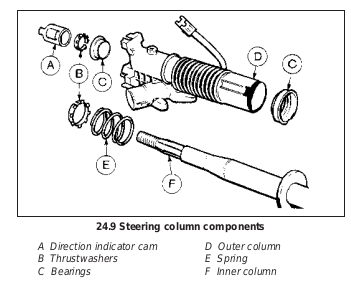
Indicator cam is a spacer.
You have to look at the construction of the column, unfortunately I can not find a diagram at the moment.
When you tighten the steering wheel nut you are not tightening the wheel down onto the shaft, but pulling the shaft up to the wheel against a spring on the lower part of the shaft.
The indicator cam spaces the wheel from the top column bearing, there should also be a shaped bearing washer under the cam. the spring pulls the wheel and spacer down to the the top bearing.
Cam, or a spacer of some type, is needed.
-
GBS loom from memory and Emerald?
Check the light on the back of the ECU
-
If you PM me your email I can link you to some files.
-
yes, it's the predecessor of the factory dash loom
-
Think I know what you are doing.
If you plan it you don't need four wires to one point
Old pics, but hopefully you will get the idea
https://www.dropbox.com/sh/yjxg4x6mkbrqwbe/AADr_DsCoHX7l_08ALMk3cnqa?dl=0
-
plugs first, the zetec enamels them up very quickly
-
As long as it's all set up correctly, in theory it should sort its self out.
-
Why is you throttle not giving full movement, it should, the standard set certainly should, so that could do with fixing.
You must set it O% to full throttle, particularly if you are using the maps from GBS.
You will also need to calibrate the map to the throttle, or they will be out throughout the map.
I have a procedure somewhere if you need it, or I can team viewer in, can usually get it about right
If you don't the map will be out, even if the TPS is calibrated
Simon
GBS Engine Link Plug - help
in Electrics
Posted
If you can give me some details of your doner, reg will be helpful, but year etc would help I will have a look at the manuals i have.
If I can find the ECU pin out and wiring I may be able to see which way it switches