


TonySuperSpec
-
Posts
248 -
Joined
-
Last visited
Content Type
Profiles
Forums
Events
Store
Community Map
Posts posted by TonySuperSpec
-
-
I have ripped out the loom supplied by RH and making my own.
So far all is going well.
My question is " How much current does it take to operate the starter solenoid and what size cable do I run from the relay?
Any advice will be much appreciated.
Thanks, Jez
The RH loom had all the wires why not use most ?
Why are you putting in another relay ?
The idea of the starter solenoid is that you don't need another relay ..
The Wiring from the ignition start position simply energies the starter solenoid...
As reards rating are you using thin wall or standard automotive cables.
Thin way 2.0 mm cable is rated at 20 Amps which is ample for the solenoid
Standard cable you would need 3.0 mm to get > 20 Amps
 :D
:D -
-
If its fine .. will try and be there as well, its a good chance to get the SS out again during the week.
Hope the lights work!!! not tried to take it out in the dark yet..
:rolleyes: -
Snapperpaul,
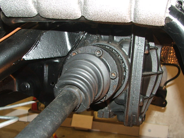
Short of draining the oil and taking the backplate off I don't see how I can check the size of the crown wheel. However here are a couple of external pics:
and I can tell you that backplate is 10" high and 9" wide.
If it is a Scorpio what will the ratio be?
John (jwts).
Why are you concerned about the ratio ?
I have no idea what mine is just finish building it get SVA and enjoy...
-
Hi,
I have a problem with my SuperSpec first engine start. It starts, runs and then stops. TonySuperSpec tells me the symptom fits a known problem of the MEMS ECU as supplied by RH around 2004/5 which is the date of my car. Tony has suggested Avon Automotive Diagnostics as a company that can solve this problem but they don’t answer the phone or respond to e-mail messages.
Can anyone suggest another company (in Kent or east London would be ideal but not essential) that could fix this problem?
I would be grateful for any/all technical information on this fault in case I have to take the ECU to a company that has never seen the fault before.
I’m feeling very discouraged by this, I’ve spend most of my spare time for the past year on this build and now I’m stopped dead by a problem that is totally beyond my skills and knowledge.
Thanks for any suggestions,
John (jwts).
Mentioned Your Problem to a mate of mine he suggested that
http://www.bluestreak.co.uk/bs/
Unit 5B, Little Oak Drive, Sherwood Park, Annesley, Nottinghamshire. NG15 0DR. Our new phone number is 01623 886470.
May be able to help they sorted out his much later MEMS units a while ago.
Hope this helps
-
Tony,
I have found the date indcated on the thermostat housing to be quite accurate as an indicator of the age of the engine. Its even correct for my current Nissan
.I'm referring to the airbag light on the instrument pod. It's blue in the lefthand cluster of lights and is a LED rather than a bulb. I may have mis-wired it but all the lights work that I would expect, even the handbrake light works.
Do you have a diagram that indicates the purpose for each of the connectors on the cluster?
John.
Not sure if I've given this but look at Visit My Website
There is one of my docs there that is the Instrument Cluster wiring
:rolleyes: -
Tony,
Is there date on the thermostat housing? Mine has 1995 on it and I suspect that is right or at least close.
BTW - Does your airbag light come on when you switch on? Mind does but I've not had to oppotunity to see if it turns off once the engine is running properly.
What's the 'Heritage centre'?
John.
Seen that but am told its no relevant.
What airbag light ?
I dont remember tracing out any wiring on the Instrument POD that went to that light ?
I managed to get a White and blue ford plug from an old Escort at the scrappy and spiced those into the Loom.
The Heritage centre is Heritage
A great deal of the Rover archive was transferred to there when it went belly up..
:rolleyes: -
Tony,
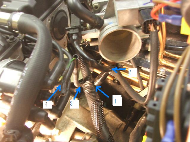
It’s not easy to photograph but I think this shows the connection from the main engine loom. The engine loom comes from around the offside of the engine and over the bell housing. The central part continues to the bottom right of the picture (it later splits into the ECU plug and the two original plugs that are removed and the loom connected to the instrument cluster and column switches).
The part that branches to the right in the middle of the pic [1] splits again [2] to connect to the air intake and throttle assembly.
The small part that branches to the left [3] contains the two wires I am asking about, you can see the ends up by the dizzy [4].
Does this help identify the wires?
John.
No in a word..
Looked at mine and can't see anything ?
The only thing I can think of is that the loom is for the turbo version and these have something to do with that ..
Had a look at all my Rover details and still can't find any reference to these certainly no reference in the technical manuals to loose Bullet connectors that I can find.
I though the Rover Technical CD had all variants but my loom was for an export spare when I finally tracked it down and the colour coding is different to UK models. So that may account for why I can't find it.
The Heritage centre does have further reference details but they are sketchy I have still never tracked down the actual build date for my Engine after months of searching. What I have established probably is that RH bought a job lot some 420, 620 and 820 variants some were for UK use and others were export probably as spares. Thats why the sump depth variation occurs, that is mentioned on threads on the site and also why wire colour codes are not consistent
Sorry I can't be more helpful
:o :o -
This is most strange..
I can't quite see from the photo were the wires are /
I have wiring diagrams for most Rover installations and I can't see Geen/brown & Green/Yelllow wires that might be in a sleeve anywhere.
Can you be more specific about the position.
Where does the sleeve branch from this might narrow it down some more.
The only loose bit on my loom was a connector coming from the crank sensor and this joined the wires (no idea of there colour to ECU loom )
All I had to do was make a bracket to hold this . From your basic description these wires don't seem to be in the right place.
If you look at Visit My Website
This has a vey basic ECU connector definition I created to help me plus others to understand the Engine loom needs...
:rolleyes: -
Hi
Mems 1.6 (the ECU supplied ) allows an engine start sequence to complete as far as I am aware .
This it seems was the original design criteria. Once a start sequence is seen i.e the crank shaft sensor is active the ECU looks for by interrogation the immobilizer code twocomplete sequences of it, I was told that is a special security signal that comes via pin 13 of the ECU (the one RH had on there diagram cut off)
So during this part of the start sequence the engine can catch etc. before the ECU receives the wrong code and locks the engine into a locked condition
The timing that allows you to try again is derived by the fact that at ignition off , approx 5 second rime out occurs and the main ECU Relay is turned off.
So if you wait 5 seconds or so this drops out the start sequence can be started again.
The RH ECU's were supposed to be supplied as either export a null code required so the immobilizer check does nothing, or a test mode this it seems can be selected by some hardware mod but mine had neither so had this fault (As did quite a number of others..)
The box of tricks has three leads.
1. Power fed from iginition on
2. An earth
3. A feed to pin 13 of the ECU
You take your ECU to them, they code there box and then perform a diagnostic via that silly plug by the ECU input on your engine loom.
They have a test rig, this codes the ECU to the box and so the code will allow the engine will run..
:rolleyes: -
Are these on the Engine Loom?
I have all the Rover Diagrans and Engine Loom wiring is all to connectors.
If they are on THe Car Loom whose are you using ?
-
You think thats tight...
With the Rover Engine in a Superspec its scary...
The clearance to the sump was very close on the rolloing road at SVA but no comment by the tester..
-
Have a look at this link...Visit My Website
I created these doc's to start the wiring - the interaction of the Engine loom to the car loom plus the instruments etc.
Must do somethimg with this site now cars on the road
-
Thats the symptom of an ECU thats not had the immobilizer mapped out
Most SuperSpec owners have had that one.
As I mentioned before
Avon Automotive Diagnostics Ltd
Tel: 01789 450808
Unit 17 Admington La Fm Indust Est, Admington, Shipston On Stour CV36 4JJ
Give him a bell he makes the box that can be mapped into the ECU to fix the problem
:rolleyes: -
Not 100% sure as its been a few years, but I belive the type 9 and several others to have a plastic worm gear just inside the the output for the speedo...these come in differant ratios and colours to correspond...have a look in your old gbox and gentle pull the worm drive out...Its probably a different ratio...HTH
Yes the Type 9 and MT75 boxes were fitted to various vehicles with various diff ratios and Tyre sizes.
The idea of the drive gear is that it engages with a helical gear and can be made with various number of teeth to provide the correct spped for the cable.
Obtaining exact details of the gears is difficult, I had big problems just before SVA after the car was checked on a rolling road and the speedo was far to far out.
From what I found out 21,22,23,24 teeth gears are made (or were made for the boxes.)
I would try and extract the old one, it comes out by removing the cover bung and gently pressing the shaft end up I used a valve grinder suction type to then pull clear.
I was assured that any type 9 or MT75 gear fits any box !!
-
Hi
Silly question have you got the feed and return round the right way ?
-
Hi..
If you search on these points on the forum you will find that most people have had problems with the ECU etc.
I investigated the MEMS system when I had problems getting started..
The Rover EMS Start sequence is..
1. Ignition on detected
2. MEMS requests ECU RELAY on
3. MEMS detects ECU RELAY on and requests fuel pump on..
4. Steeper on throttle body advances the pedal position to start
5. Fuel pump off - normally 1=3 seconds later.
6. MEMS looks for immobilizer this should be mapped out but mine and others were not.
Starting will then commence by this time the starter motor should have turned the engine over, the crank sensor reports this and MEMS starts to inject and fire the plugs etc. in an open loop control to get the start you want.
You can check EMS basic op by ... Ignition on, then fully depress the Accelerator 5 times you should hear the steppers resetting etc. and the fueel relay will turn on and off.
You also get problems if the accelerator pedal is set to far open at its rest position, Looking into the air intake with the pedal at reset the butterfly should be closed..
If you think the MEMS is at fault then contact,,,
Avon Automotive Diagnostics Ltd
Tel: 01789 450808
Unit 17 Admington La Fm Indust Est, Admington, Shipston On Stour CV36 4JJ
He sorted mine and supplied the box of tricks that sorted the immobilizer problem
Cheers
:rolleyes: :rolleyes: -
Yes I got the bit from RH
This was to short and did not fit
THe £1 mop bucket was exactly the same shape as the RH supplied bit..
-
In my superspec made mine from a £1 Mop bucket + a couple of brackets
Looks very reasonable...
Could be a solution...
-
Hi All
After 5 weeks off red tape by the DVLA I have final got my super spec 05 kit registered, passed SVA 1st Sept Registered 8th Oct. Poor lady at the DVLA at Wimbledon has been pulling her hair out because the person who completed the build report had not submitted it. Chased it for over 2 weeks, Wimbledon DVLA use an out site agency who are based at Orpington to complete the inspection.
Only other problem I got a Q plate but, hay ho life goes on.
Again many thanks to all on this forum who have helped me over the last 2.5 years, with out this help I would have stopped the build ages ago.
Cheers
Stephen
Great news and the Sun is shining... Is the Q plate because more than one part is reconditioned ?
-
Hi hope this gives you some ideas...
-
Hi to all who replied to my post.
Many thanks for all your suggestions, comments, sympathy !
I'm back from my hols now, so it's back to the task of finishing this build - with your help !
Thanks
Brian S
(incidentally - I'm in Brum)
I'm in Sutton
My Superspec is finished so can give you a hand if you would like help...
:rolleyes: :rolleyes: -
if you go the route of a k, then you need everything from the donor, including the keyfob if you want to use the ecu
bell housings are availlable, keep an eye on ebay?
the 1.4's appear to be the strongesy of all the k's, but they still only overheat the once, before the headgasket needs doing (last bit from personal experience
where in beds are you ?
Avon will map you an immobiliser fiddle to avoid key fob problem..
-
Hello again Will, glad you are still here with you happy faced avatar
You've helped me a ton already, I can't believe I'm still building it, its insane! Going to make a concerted effort now or it'll never be finished which is a waste.
Popping up could be massively helpful, to give an idea these are what I'm stuck on currently:
Fitting the exhaust backbox to the car
The handbrake (trying my own design, haha), might just need a rivnut tool here
Fixing the fuel tank without being able to weld
The brake pedal fouling on the steering column
The pedal box not being tall enough to attach the cables to
General wiring (although I am making decent progress there now, jut slow and confusing).
What air filter to use
What fuel pump and swirl pot to use, happy to buy new, just need to know what I need
Brake servo vac pipe, this totally doesn't fit, love it.
Brake filler pot thingy not fitting into where its meant to.
I think that about it for the moment. If I had those problems sorted right now I would be a happy man!
Can answer some based on the list..
back exhaust - you should have a bit of bent angle iron .. Don't use it as obvious reverse and drill new holes then one rubber bobbin
Can't find a pic but will try and source one.
Handbrake why ! fit as is for SVA then change..
Pedal box.. You have got the spacing wrong or fitted clutch as brake easy to do..
Not sure what you mean not tall enough the cables go through front..
Air Filter I used supplied
My tank had the fuel pump fitted..
Why does the vac not fit servo its hard to get into servo but mine fitted
Made my own fire wall so made my own brake resovior holder. What pipe work re you using resovoir to master I used 0.5 inch copper and 11mm gas into master.
If any of this helps email any further I will take extra pictures if I can... and send them
email is tony.grimer@tiscali.co.uk
Enjoy...
:rolleyes: when its finished and on the road as mine has been for 3 weeks its great fun.. B)
 :D
:D -_-
-_- :rolleyes:
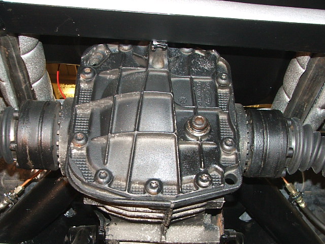
 .
.
 :o
:o 

Wiring Advice
in Electrics
Posted
The SVA requires that the anti-theft device has a mechanical component... i.e a steering lock is OK but a battery isolator is not..