Thrashed
 RHOCaR Member
-
Posts
987 -
Joined
-
Last visited
-
Days Won
14
Content Type
Profiles
Forums
Events
Store
Community Map
Everything posted by Thrashed
-
I am planning on heading over this morning.
-
Stick us down for 3 please Richy. Look forward to catching up with everyone.
-
Looks like I can actually make this one and I will be in the kit!
-
Thanks for organising again Richy. Good to see everyone.
-
Hi Richy. Can you add Bob and Di to the list please cheers
-
Hi Richy Please count Dee, Paige and myself in. Thanks
-
Now Sold
-
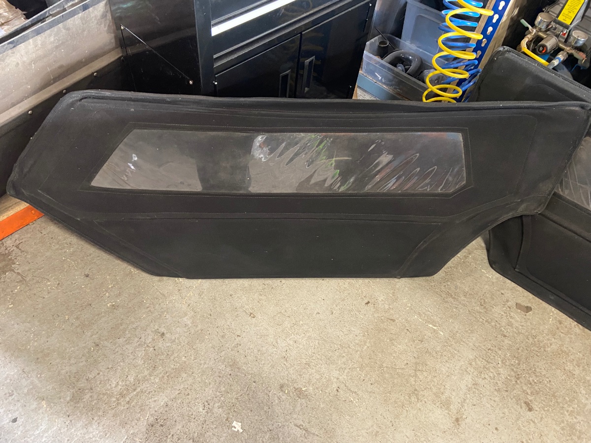
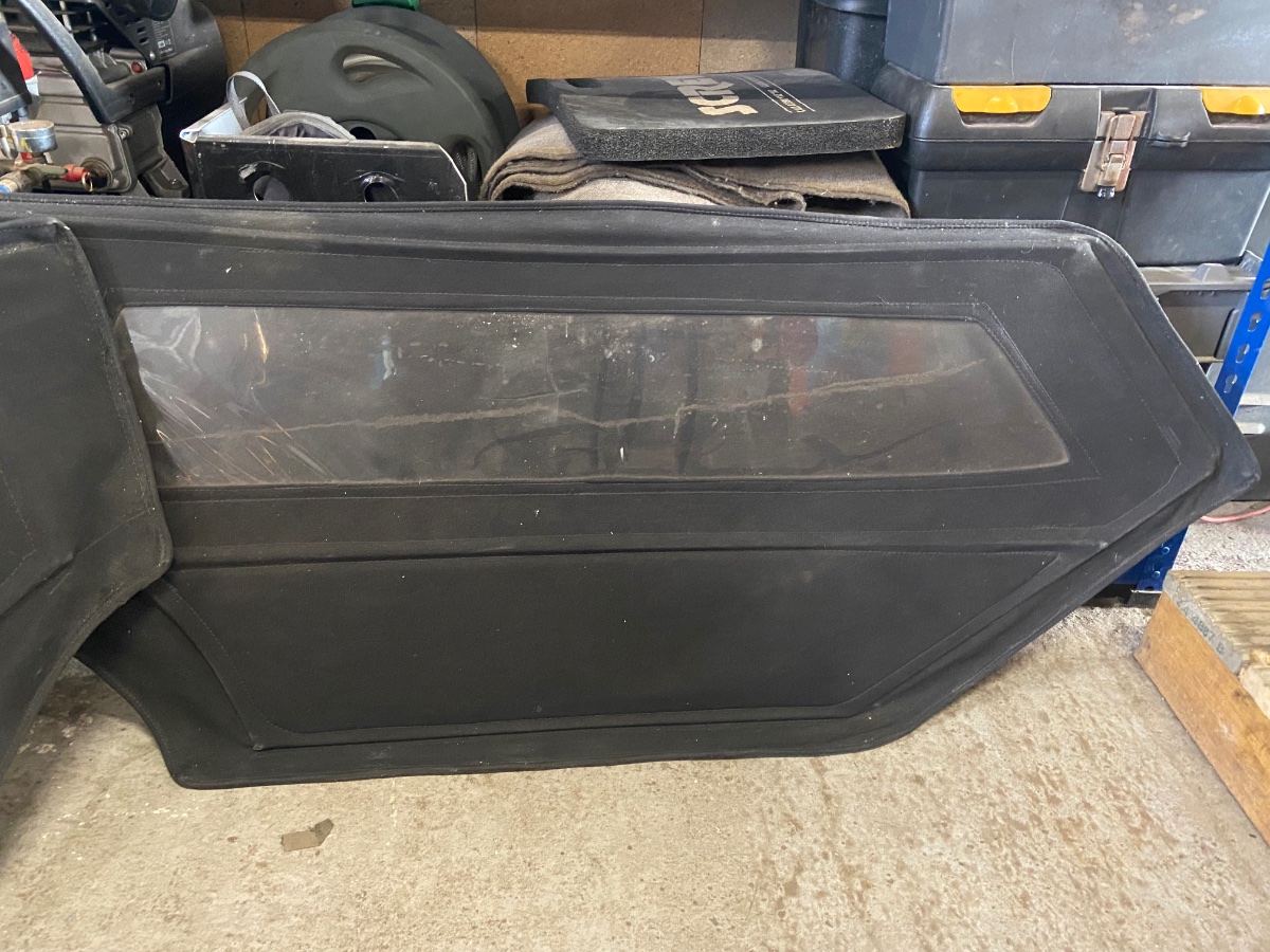
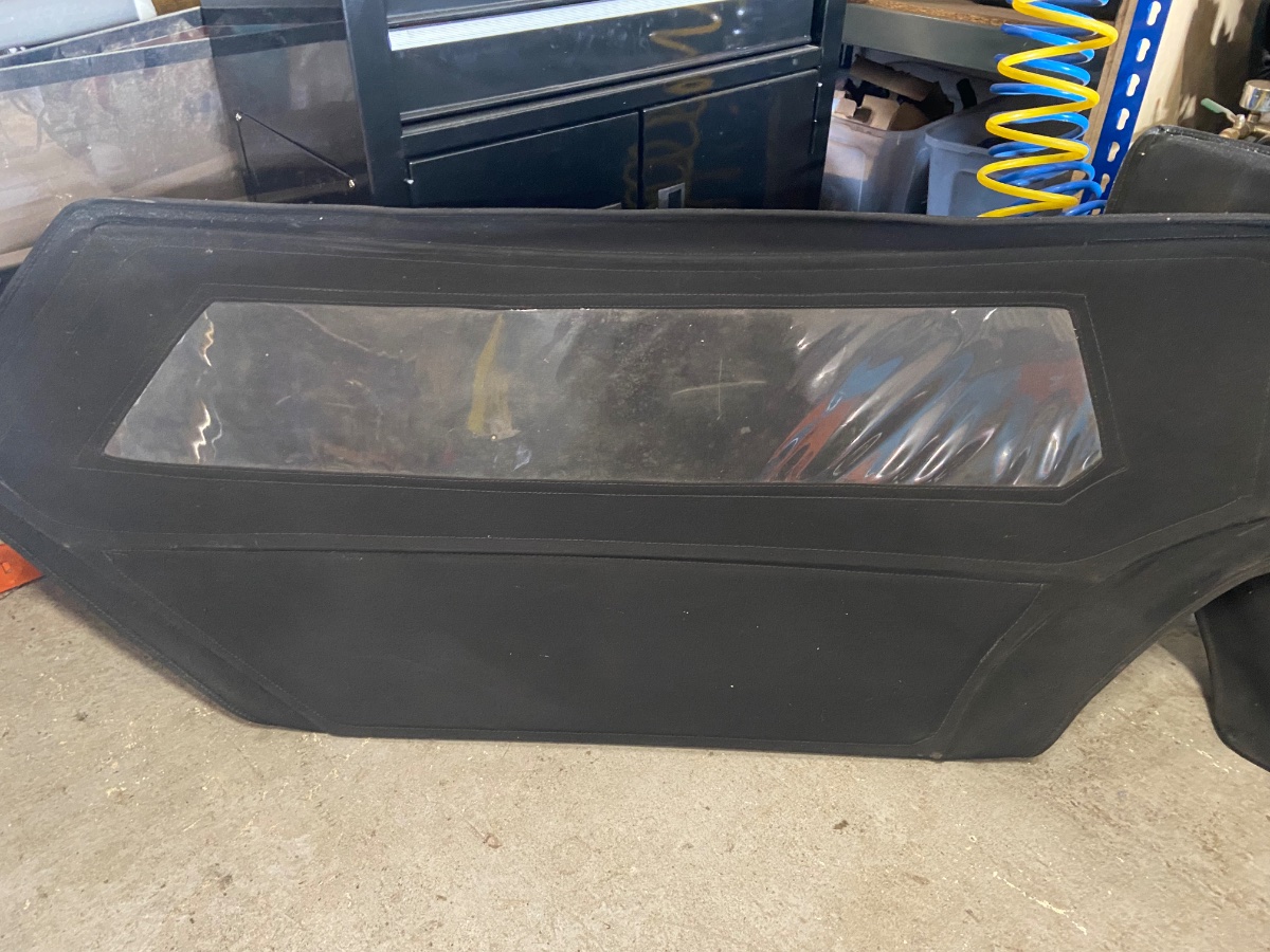
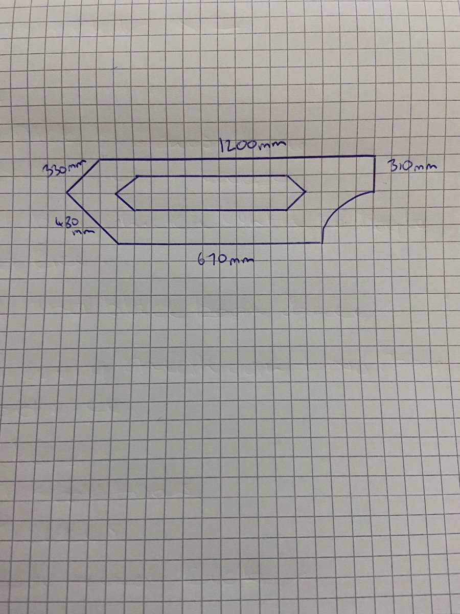
I have a set of doors for sale. They feel like a moleskin type material. They have never been fitted. dimension’s in the pictures are rough to give an idea of size and shape. Windows are covered in protective film. Ideally collection and not sure they would survive postage, but happy to post at buyers cost and risk. £100 for the pair.

-
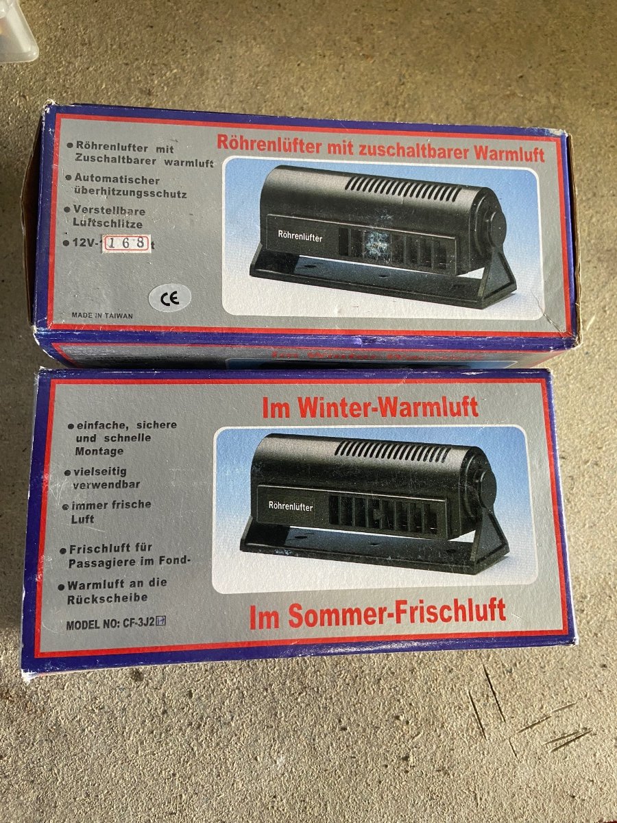
I have 2 new demister units. They are 12v 168w. Bought from car builder solutions but didn’t use as went a different route. Full details of the units can be found on the car builder website https://www.carbuilder.com/uk/electric-demist-heater Happy to sell individually or as a pair. £15 each including postage or £25 the pair including postage.
-
See you there Richy. Me, Paige and Bob will be carvery’ing beforehand if anyone wants to join. We plan to get there for 5:30-6pm for food.
-
No promises. Depends on how the phone call goes tomorrow!
-
I got fuel today so I am good to go. Morrison’s let me brim the tank in the Skoda. Anyone going for Carvery before hand?
-
See you there Rich. What time you planning arriving?
-
October/ November 2020 Now, it has been an age since I even opened the garage door. The good news is I got through the final exams and managed to pass them all first time. The down side is that the exams, running the business and a very heavy workload meant the kit has not had a look in. The work situation is not likely to slow down any time soon, so I started looking at other options. Option 1 - sell the kit as a nearly finished project. Option 2 - just mothball the kit work on it as and when I get spare time Option 3 - find a 3rd party to finish the kit A separate issue and solution has also arisen as we need more office space so one way or the other the kit need to be moved as the garage is getting converted to office space. The good news is a local friend has a storage unit. It is on a farm with 24/7 access and only a couple of miles down the road. It is an old barn that was used to store potatoes. So, the kit is off to the spud shed! This means after loads of consideration I will keep the kit. All of the other option for a weekend toy just don’t work for one reason or another, although getting back into bikes I very tempting! This is when all the stars and planets aligned to answer my prayers. As you will have seen, our very own Richy B has opened his own business for all things, kits, classic, American and cool! As soon as I got wind of this I jumped onto the phone and discussions started to get to the top of the list. Richy has some tidying and organising at the Unit so we have set a date for the kit to get moved over to him in Tamworth to get the kit finished! I have given him a very poor scrap of paper with a to do list, but the main part was that Richy has complete licence to do what he sees fit to fix the issues I will have caused and finish the bits on the list. Anyone who knows Richy or has seen his 2B with a V8 will know his attention to detail and skill level so I know the kit will come back better than I could do myself or even imagine. No timescale was set so this would allow Richy to run this as a project in the background whilst still working on other paying customer cars. Stay tuned for the car being moved and Richy working his magic.
-
26.07.2020 Been a while since the last update. The last few months has mostly been faffing about to get the screen sitting perfectly. This has involved the screen coming on and off about a million times!! It turns out the reason it would not sit straight is that the car is not square! To be more accurate it is the scuttle. The measurable centre point is around 20mm from eyeball centre. Weeks of measuring and trying did not work, so i decided to make it look right, rather than being measured right. Just hope not one takes a tape measure to it! After i figured this out, i then fitted the glass for the final time. I left the rubber trim long at this stage. This will help when it comes to painting. I will be able to mask under the rubber, spray the frame and then cut back the rubber for a nice neat finish. This is what it looks like now Overall I am pleased with the result, but it has been a lot more work that I first thought it would be. Next up is to fit the wiper. First off I started with the wheel boxes. It all sits reasonable well and sweeps as well as i would expect. It's not perfect, but for the number of times it is likely to be used it will do. The next job will be to fit the wipe motor. Luckily I have enough space to fit either side of the scuttle, but my preference is the passenger side. The motor is reversible so once it is fitted it can be adjusted to ensure it pushes/ pulls the correct way.
-
18.5.2020 So a little milestone this weekend. The bulk of the windscreen frame has been completed. It wasn't that bad a process in the end, i was conscious i only get one go, so it had to be right. Just a bit of time and thought on the best way to do it was all it took. Below are a few pictures. Trying to do it and documenting the job is not easy as you need 3 hands at the best of times. First part was getting the side frame and lower rail clamped together. I used an M4 bolt, drilled the hole at an appropriate angle and clamped it all together. This pulled everything nice and `tawght!. I played around with which way to feed the bolt and settled on the head inside the lower rail. This allowed me to countersink the side frame which with a ground down bolt keeps is very low profile to the side frame I was concerned about how much clamping force I could apply. I wanted to make sure it had enough to hold the glass in place, which is why I went for the bolt, rather than a screw. I was not happy a screw would have enough threads biting into the frame. My first attempt proved I chose well as I managed to bend a bolt tightening it up. This was a double edge sword as it proved i had enough clamping force, but also that i didn’t need to use maximum effort to get the result i needed and wanted. Next up was to be brave and fit the actual glass!! I was very nervous and very careful, but it went like a dream. I am well happy with the result and fit, so next job was to fit the rubber into the channel and make sure it all lines up. I also trimmed the ends of the side frame. I decided to go with the curve of the lower rail. A bit of lube on the glass and rubber and it all slid together nicely. The next job will be to pull it all aparts again! This will be to drill and tap/ helicoil the side frame for the side supports. I am not brave, accurate or skilled enough to risk doing it with the glass still in, but felt like it needed to be complete so I can fit the car perfectly. Once this part is complete I will be able to trim the rubber and cut down the bolts. Then it will be onto the painting! As a side to the windscreen I had a little delivery from Dan. He was kind enough to mill an EGR blanking plate. It is just a cover/ beautification plate, but man it looks good. It fits a treat and really finishes the side of the engine. It is a shame it is hidden away behind a fuel pipe and wiring as it deserves more of the limelight.
-
3.5.2020 A little progress this weekend. The fittings for the brake and clutch lines arrive during the week. This was a case of screwing them in and nipping them up. All easy enough and the net result looked good. Next job was to add some fluids! I started with the coolant system. The system took just over 7 litres. I thought this sounded like a lot but when i checked the Haynes Book of Fairy Tales, it suggests that an MX5 system takes 7.5 litres. The good news is that i have no leaks. This is without the engine running, but still a good sign. Next fluid was the clutch. The gear stick turret needed filling with oil. The HBFT suggests that this be filled with 300cc of gearbox oil. The clutch reservoir was next to get filled. I also did some research on the fluids. It suggested the Dot 4 is able to deal with higher temperatures, but the Dot 3 is more resistant to moisture. I used a Dot 4 fluid. This was the suggested oil in the HBFT so it seems good enough. With fluid in, the next job was to bleed the system. I turned to the trusty Gunson Easibleed. This has never let me down and has always made brake bleeding quick and easy. That was except this time. The caps that are supplied with the Easibleed are far too small for the Compbrake reservoirs (girling style) which are about 65mm. The option was to but a cap big enough or a more modern version. I decided to take the opportunity and upgrade to a pneumatic fluid bleeder. This will connect to the air compressor and will pull the fluid through the system, removing the air as it goes. In the meantime I went with a bit of pedal pushing. This `highlighted’ the first connection that i had not done up tight enough. It is amazing how such a small amount of brake fluid can travel. 5 minutes later, all cleaned up and ready to go again. This bled much of the clutch, but will finish once the new bleeder arrives. Not having enough Dot 4 to do the brakes, i have left this for next weekend when the new bleeder and Dot 4 arrive. Next little tinker job was to sort the steering wheel buttons. I have 2 buttons on the wheel. The right hand switch is a momentary button, which will be used for launch control and the right hand is mostly likely to be used for a map switch function. Probably a normal mode and sports mode with flames and pops! The momentary button is from when I had the Omex launch control. One of the pins on the back was broken. This was probably from when I soldered the previous connections and the plastic became hot and brittle. This time i will be using a different method. I saw this on a youtube video and thought it would fit nicely for my application. The pins on the back of the buttons are 2mm. All the usual crimps are too big. The method i saw was an econoseal pin. This then fits in the slot in the middle of the pin on the back of the button. The pin then folds over 180’ and is crimped on. A bit of heat shrink and a rubber boot later and that is one side done. I will probably hot glue inside the boot as a bit of weather protection as the securing nut for the button is only 2mm thick so not much for the boot to grip onto. Just waiting for the other side to turn up and that will finish that job off.
-
27-4-2020 Aluminium tube turned up today, so had a spare hour this evening to have a play. I needed to turn this, a 1.5m length of 8mm OD tube into a tube that followed the engine from the water manifold at the back of the engine along the rocker cover above the exhaust manifold, around the front and then to the expansion tank. When i bought the tube i made sure it was 6063T6, to make sure it would form easily. I also have a mini tube bender that forms 6,8 & 10mm tubes. This is the first time using this and i had no idea how difficult this was going to be. I decided buying 2 lengths of 1.5m tube was a good idea, one to practise on and then the final piece. It turned out not to be as hard as i imagined it would be. The tool has reference marks for where the bend starts and degrees all the way round to 180’. It was just a case of measuring the length and getting to grips with the way the bends are formed but first go i ended up with exactly what i needed. When placed on the engine it looks good even if say so myself. I just need to add a couple of rubber lined P clips to hold it all in place and some rubber hose to connect to the water manifold and expansion tank. The final part of the plumbing will be the final connection from the thermostat housing to the bottom of the expansion tank. All easy enough as it is just cutting a bit of 16mm tube and silicone hose to the correct lengths.
-
26-4-2020 This weekend i was working on the coolant system to get it finished. Main job is checking the plumbing routes and fitting the expansion bottle. The original Fiesta coolant system has a heater in the system. My car will not have this so needed to find the correct way to plumb the engine without the heater in the system. This is how Ford plumbs the system: To me this just looked like a jumble of hoses! I also had the added issue that very few of the hoses fit, now the engine is in a rear wheel drive configuration and my radiator is in a different orientation. I needed to find a way to plumb this but still make it work! A bit of internet digging and research i came across a good diagram on the Locost builders site. This was useful as it showed the water flow path to make sure i had mine plumbed up right. The only issue is that it does not show the coolant path for the water to oil cooler. This was a mixed blessing as i wasnt 100% on using it and the space for running hoses was very limited because of a chassis rail. Speaking with a few kit owners, running Duratec’s for track days, seem to agree that on the road, the oil cooler is not a major requirement, but much more useful on track days. The 2 main reasons given have been that the water to oil cooler helps to warm the oil quicker as well as keeping the temps down on track. As mine is a 99% road car, not having the cooler was an easy option to leave out. This is easy enough to review if i have issues when on the road. With this plumbing now sorted the next decision was the placement of the coolant expansion tank. Originally i had planned to mount this on the firewall, but i really wanted to keep this area clear for a clean look. Finally i decided on mounting it just in behind the radiator in the engine bay. In this location i can make sure it is the highest point in the coolant system, but the added bonus is that the tank will be hidden under the nose cone. This keeps everything nice and tidy. This location then presented a further issue which was i had nothing to mount it too! The location i want would be in fresh air, so mounts are needed. The tank only had two mountings moulded into it. One is a strap what would allow a 3mm thick piece to slide in and the other is an ovalled M6 hole. Having limited imagination and when using 2mm bent aluminium the tank was very wobbly and this was before it is filled with fluid. Thankfully Richy B came to the rescue again with a much beefier design. At first glance, it looks like overkill, but Richy always knows best, so i followed the plan. The weekend then involved 8 hours!! To get to the finished state. All in all, i am pleased with the outcome. It still surprises me how long such a small job takes, but then Stu (The Duck) reminded me about Project Binky, and they have way more brackets than me! All that is left now on the coolant system is the small 8mm tube that runs from the manifold at the back of the engine by the bulkhead to the expansion tank at the front of the engine. This is going to be done in one piece which will involve a few 90’ bends with short rubber hose connections at each end.
-
I would say yes. Have a good read of a workshop or Haynes manual and just take it slow and methodically. Depends on your previous experience and confidence. Plenty of people in here have that will be able to offer help and guidance to members.
-
The head work I got a local shop to do but all the assembly and disassembly I did myself. I am reasonable with the spanner’s but no mechanic or engineer and I found it easy enough. Bike carbs were a bargain compared to Webber’s etc. My Dad had Webber’s on an old school Westfield as it was on the rilling road every year trying to keep them in balance. Never had that issue with the bike carbs.
-
I had good results from an FR32 cam, bike carbs, 3 angle value seats and a ported head. Also a good rolling road session to bring it all together!
-
12.4.2020 Today was planned to be a day off. A few messages with Stu (The Duck), and he convinced me to get off the sofa! Todays job was basic setting on the ECU. This would allow us to check the engine will still start after all the wiring and ECU resets. This was a good hour session, which proved the engine would start and run. It will need some tweaking as it is rough, but i need to finish the coolant system in order to do this. Hearing the engine run is always a great motivation, so a spot of lunch and next job was the windscreen! I have been avoiding this as it feels like a big job. I have read Dan’s (Brumster) on RHOCaR and Richards blog (https://richards-gbs-zero.blogspot.com/2013/06/windscreen-prep.html). Both give very good guides on what to do and how to do it. I was lucky enough to `steal’ Dan’s windscreen glass template. He has a couple of screens made and drew an outline onto cardboard. Stage 1, cut out the template to shape. Dan was even good enough to give me the requirements for the glass type and markings. Step 2 was to make a full size replica. The screen thickness is 6mm so a sheet of MDF, a marker pen and a jigsaw, created this. Being sensible, this is likely to be a template I keep for future windscreen replacement, or if someone else needs a template, so i copied the specs onto the MDF. Step 3 was to try and make the top rail fit the curve of the screen. This was easy enough and I added a couple of alignment marks for reference when it comes to final assembly. The basic shape was easy enough to form as the main surround is already pre-bent. I used the racket strap to keep the tension on the frame sides I offered up the bottom rail, but this is going to take some more research as these are several versions of the same theme when it comes to cutting and securing the corners. The most common version is to drill at an angle and screw to secure the side to the bottom. Richards blog shows using a plate to add a bit of strength and i have been given the idea from Gaz (Midlands RHOCaR member) to use a 90’ plate. All seem like a good idea and will give the fixings something extra to bit into. So, whilst i research the method i will adopt, i couldn't help but trial fit it to see what it looks like on the car. At first i just could not fathom out why the screen looked so wrong! Must have sniffed too many fumes for the tuning tests earlier in the day!! After figuring it out, got the screen on the right way and it doesnt look too bad. The rake of the screen looks good when the bottom of the support bracket is horizontal. The previous holes for the aeroscreen, should be covered and hidden by the screen, so this will decide the fore and aft position on the screen. Final positioning will be left until I have the wipers and demisters, so i can make sure everything fits. Next thing was to check the height actually fits me. I needed to check sight lines would work for me and that my head is actually behind the screen when I sat in the driver's seat. I also need to check that i would have enough height for when the surrey top is made. This would also give me a chance to check the pedal box now it is in its final position. You can see above my head a piece of back conduit. This is sat as a straight line from the top of the roll bar to the top of the screen, which will be slightly higher yet, once the screen frame is on. This gives me plenty of headroom, which when I get a surrey top on, will mean it shouldn't feel too claustrophobic. Also it means i will be behind the screen and out of the wind blast. Think i will do a parts needed list and get ordering. I need to get onto ordering the wipers and demisters. I also need some adapters for the master cylinders to hoses. I am sure, once I start looking, I will have loads of bits that I need. With the lockdown as it is, I just hope I can get the parts delivered. I have enough bits to be getting on with in the meantime. I will shape the screen supports, finish the plumbing, finish tidying the wiring and more. Lets see what i can get done during lockdown.
-
I did consider this option but then I realised that the pots are off centre so can rotated to fit in the space. Thanks for the tip.
-
11.9.2022 Only a couple of hours on the Zero today. Most of the garage time has been tidying up! I have 3 `scrap’ boxes. One for metal, wiring and wood. The metal box was starting to overflow and get in the way. I got a bit brutal and threw away some of the smaller and less useful parts. This means that I can now get everything into one tote box. The wiring was actually 4 smaller boxes. Again, condensed this into one box and the wood was tidied up in the corner in a neater fashion. I also condensed the cardboard i have for my CAD modelling, which has given me a bit more room at the back of the garage. I then spend nearly an hour trying to figure out how to fit the remote fluid reservoir for the clutch. First off I thought about using a spare threaded hole off the coil mounting bracket. After speaking in a messenger group with the Midlands RHOCaR group, the general consensus is that just one bolt would not be enough and fixing it to the engine was not a great idea due to the vibrations this might cause. The first 2 pictures above are the area I have to work with. The second 2 pictures were original suggestions. The option at the end of the pedal box cover on the outside edge would not work as the hose down to the clutch master cylinder would interfere with the steering column. The second option would cause issues with interfering with the pedals. This gave me the idea below. This would mean a small hole in the battery tray panel, but as it is not likely to be coming off anytime soon, this does not cause any issues to me. A couple of Rivnuts and M6 bolts and job done. The bracket itself was from the original pedal box kit. It had the bracket which allowed for 3 reservoirs to be connected in a line, so a bit of a shop with the angle grinder and a single bracket was created. Not much progress for 4 hours work, but a step forward is progress, so onwards we march.