MarkBzero
 RHOCaR Member
-
Posts
2,235 -
Joined
-
Last visited
-
Days Won
49
Content Type
Profiles
Forums
Events
Store
Community Map
Everything posted by MarkBzero
-
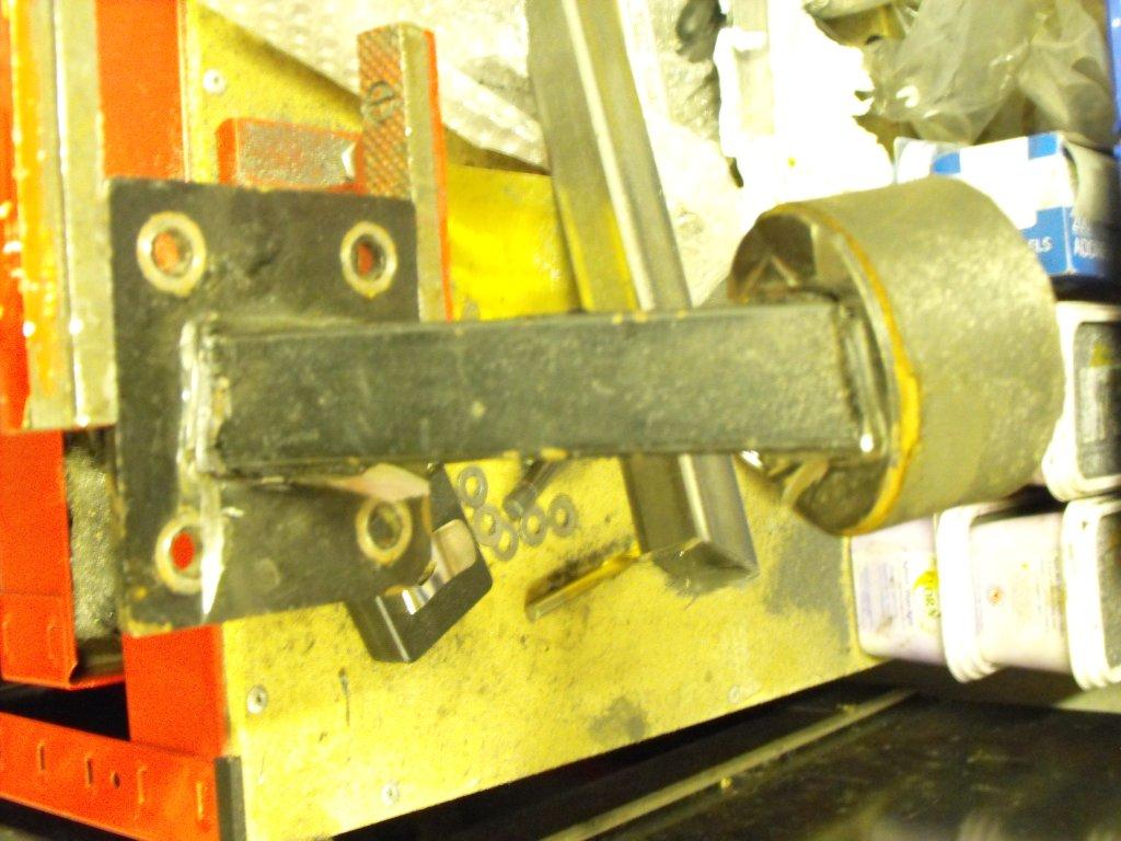
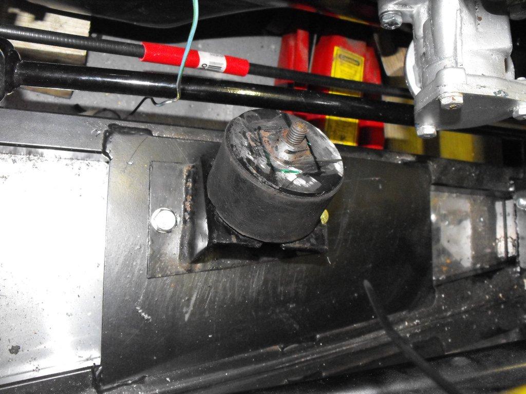
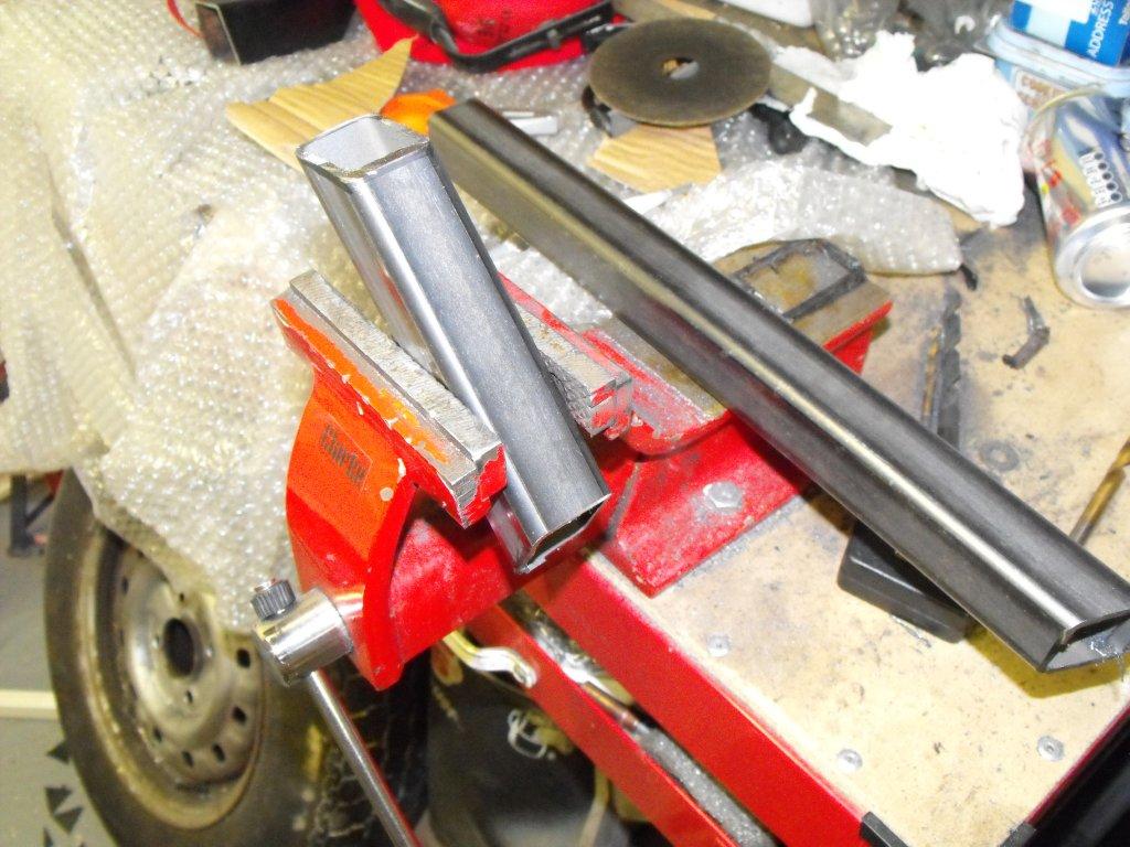
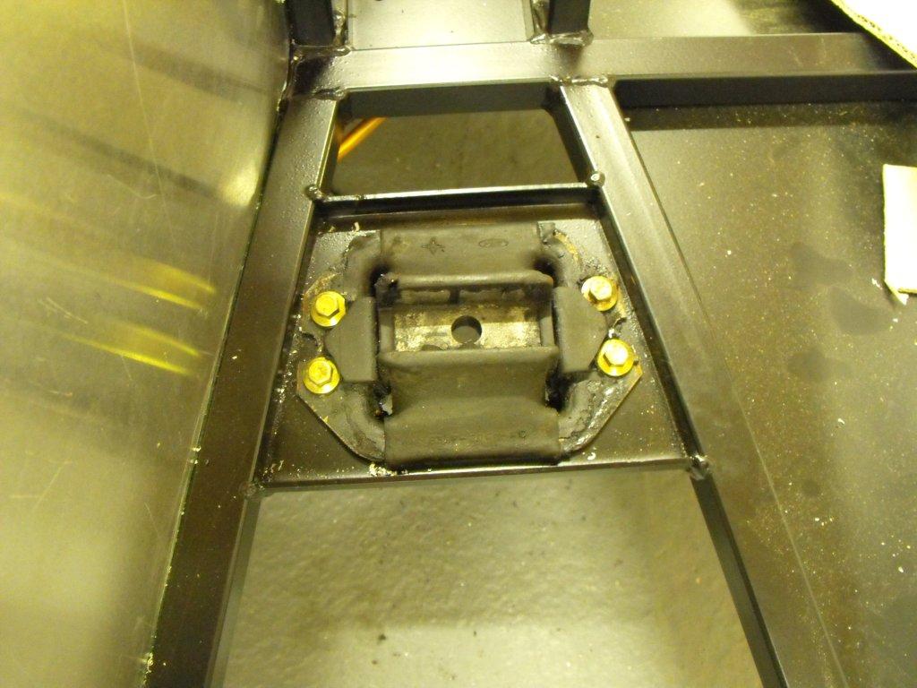
Then I test fitted the engine, to make the engine mounts. GBS never had engine mounts for a crossflow in a zero, so I bought an old set on eBay from a 7 style car. I then fitted the angled chassis end with three high tensile bolts to the chassis plates, and cut the old engine mounts so I had a plate fitted to the rubber mount and to the side of the engine. Then with some careful measuring and laser level I centralised the engine front to rear and side to side. Then cut some square tube to the correct length and a colleague welding them for me. A coat of black engine paint and new Landrover bushes were fitted.

-
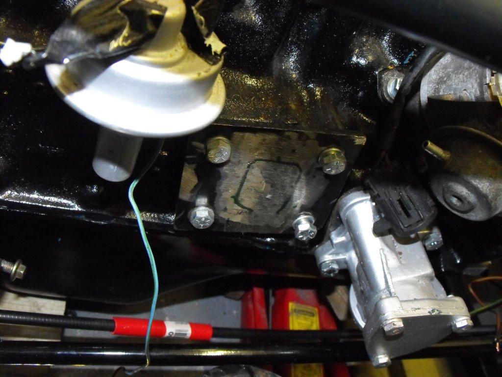
At this stage I wanted to fit the gearbox to identify the prop length. Only one mounting bolt fitted from the mount I fitted into the chassis earlier and I supported the bell housing on blocks of wood. I then marked the bell housing (starter area) to allow the gearbox to fit properly within the tunnel, cut and then made a simple plate which I bonded to keep the rubbish out.
-
To be honest I am not actually sure but I followed GBS figures but on the VOSA Inspection and results sheet they measured; Wheel base - 2370mm Distance from Datum point to axle 1 - 140mm Centre of gravity height - 310mm Kerb weight axle 1 - 295kg Kerb weight axle 2 - 295kg Weight with driver axle 1 - 325kg Weight with driver axle 2 - 370kg Design weight axle 1 - 450kg on IVA application form I had to change and sign declaration to 520kg Design weight axle 2 - 600kg Design Gross weight - 1100kg I suspect it also has something to do with braking effort.
-
The declared weights on the IVA application form was incorrect, I took them from the forum. Axle 1 450kg axle 2 600kg however after doing some measurements I need to sign a declaration form that axle 1 is actually 520kg. Not an issue just a form to sign, please remember I have a Zero fitted with crossflow and stainless steel body panels.
-
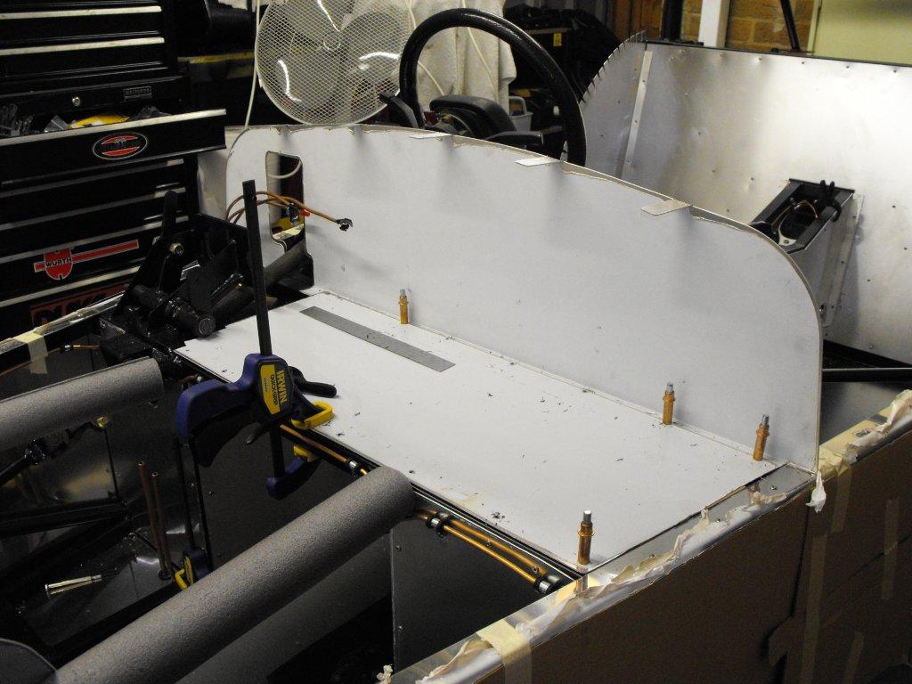
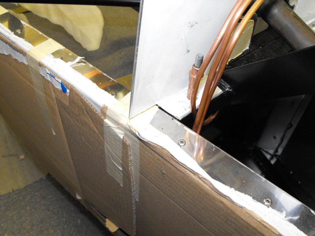
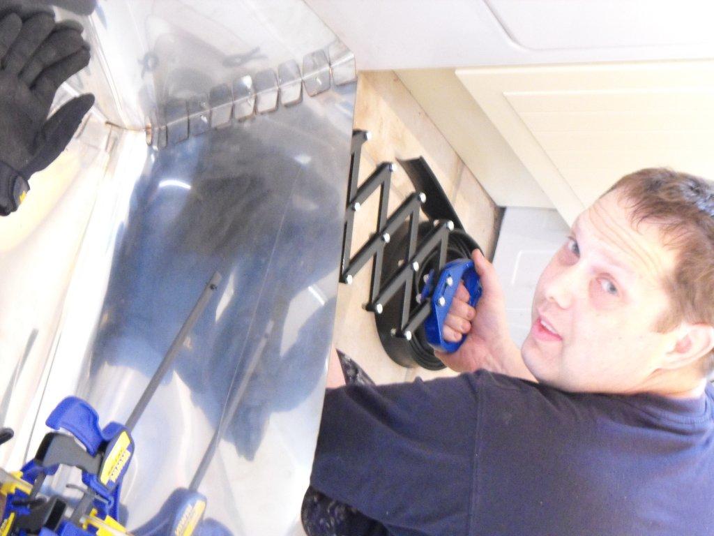
Moving on to the scuttle and fire wall. Firstly I completed a test fit using good old cleko's (great tool), I had to remove the a the ends to sit flush with the chassis (second picture). Then I had to manually bend the scuttle, this took a few attempts to match the curve of the fire wall. Please remind me why I went for stainless steel again! I secure the whole unit unit with three bolts and panel adhesive beads to cover any imperfections/gaps.
-
Re-test booked for Tuesday 22nd, need to find a local trailer.
-
Towards the sensor.
-
Hi Phil, I have fitted the two magnets to the diff flange 180 degrees apart, drilled a small hole and then araldite them into place. Then made a simple bracket to hold the sensor, which I have modified a bit since the photo was taken but you get the idea.
-
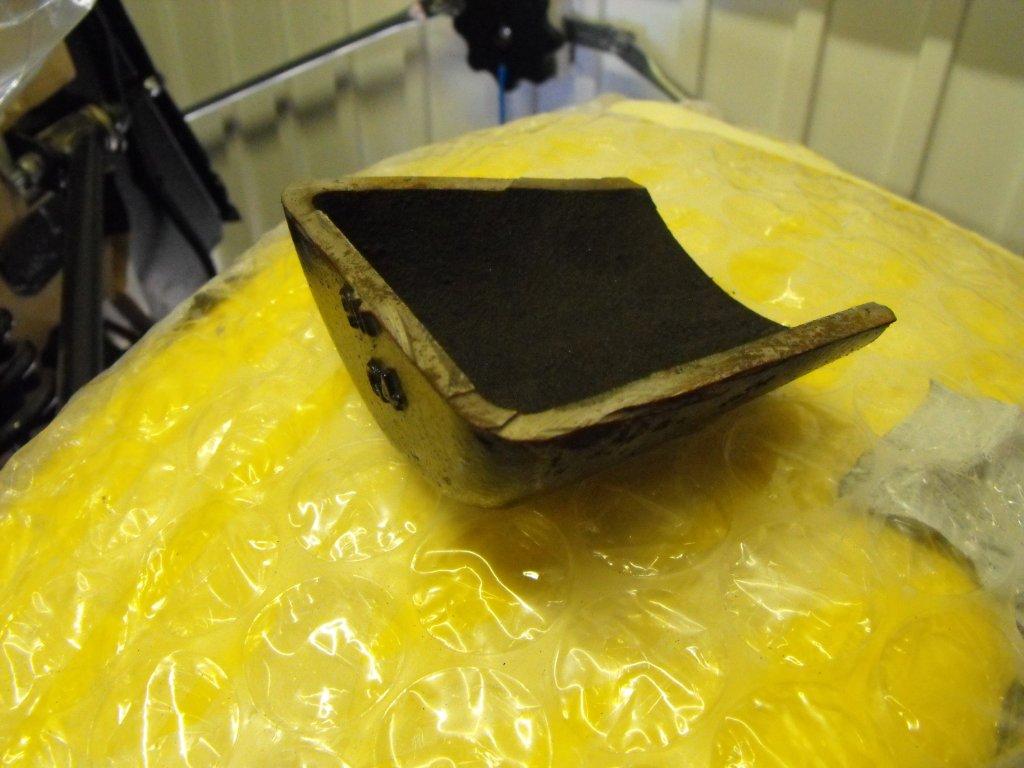
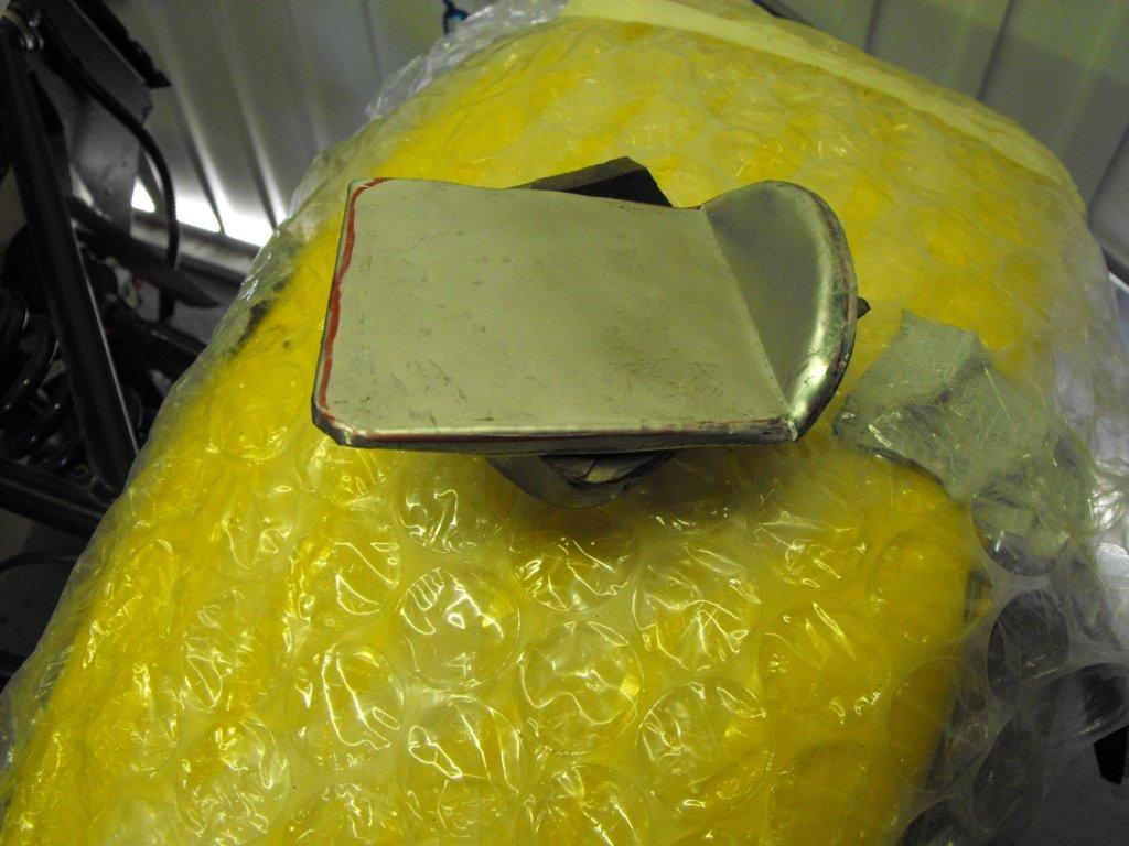
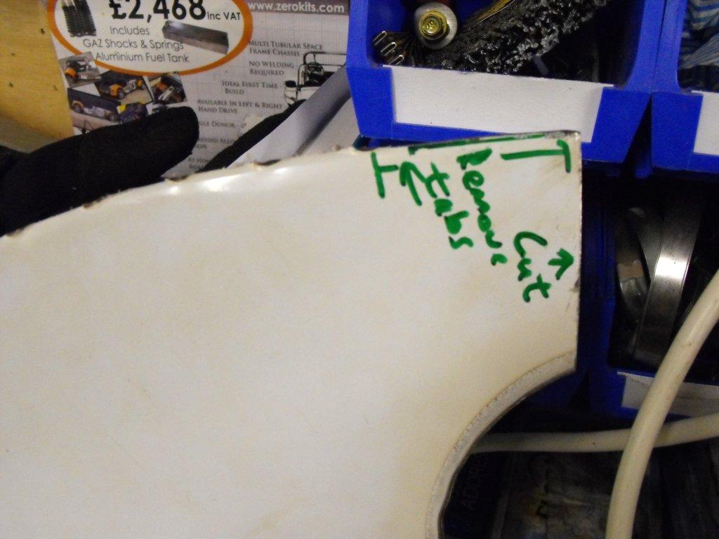
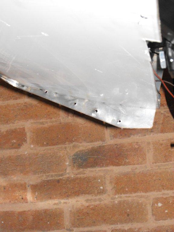
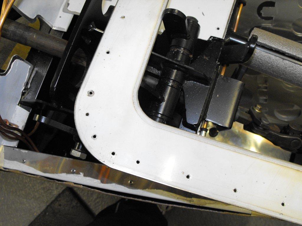
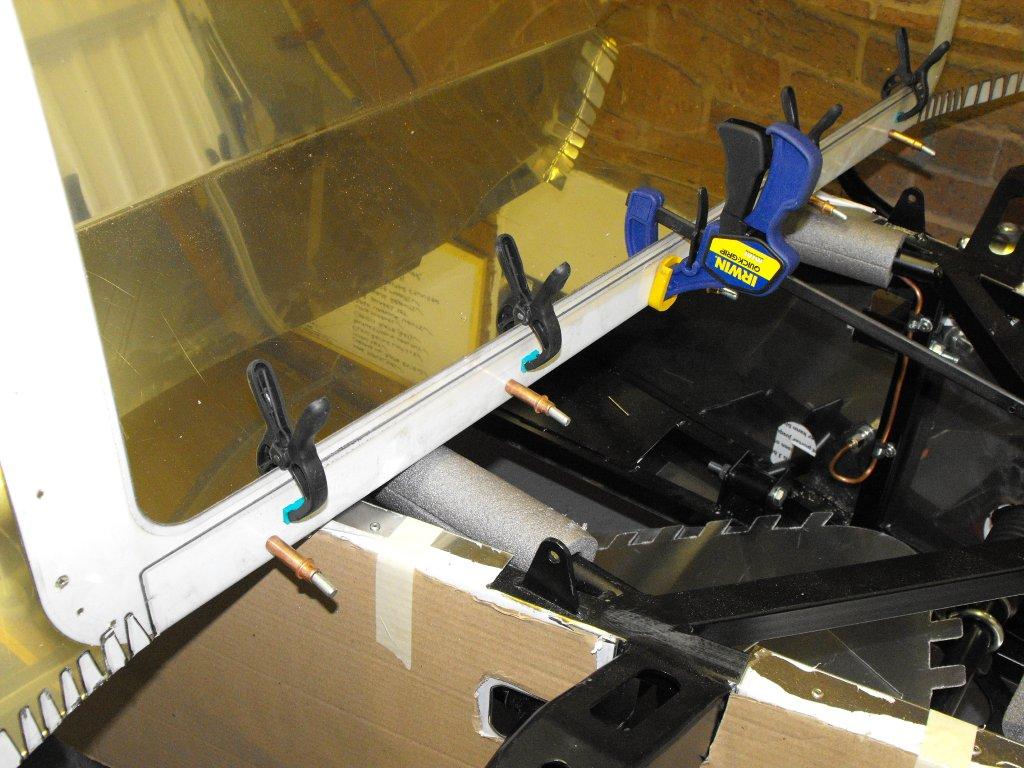
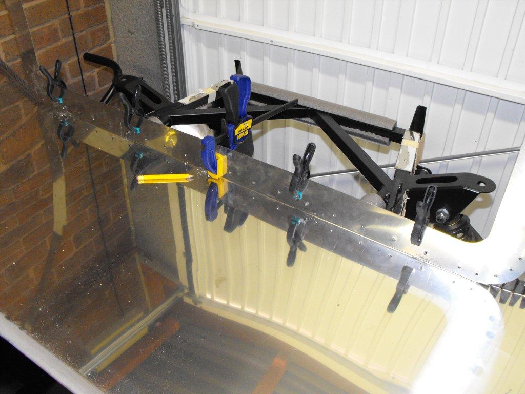
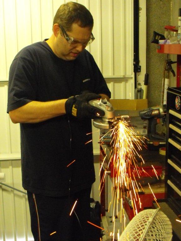
Next I had to fit the the 1/4 circle panel to complete the rear end and join the side body panels. I can only assume these are separate because GBS cutters cannot handle the length of sheet steel that you would need. Firstly I had to bend the tabs and then cut off a few so they did not cause any overlap with the rear panel, which would have been impossible to hide. Then fit with a few discrete pop rivets which will be hidden by the wheel arch later. Then I continued with the tadpole beading all the way down the edge, and riveted the rear top strip. Not the best job, too many fiddly bits and really not much to rivet to, GBS have now put another chassis frame here on later models which should make it easier.
-
Gutted my car is still not road worthy, IVA re-test soon then I'll be there Rich.
-
Very nice, looks like a new car.
-
Rolling road session completed and emissions now within limits. The Accuspark electronic dizzy is preventing anymore performance with the engine and twin Dellortos, I will need to upgrade after IVA re-test. The mechanic at the garage thinks I would have been better with the old dizzy and electronic module that came with the car.
-
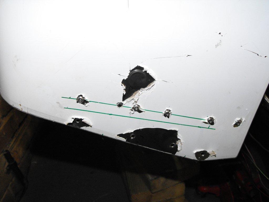
You can see in the picture below how I fitted the bottom rear panel then realised it would not sit against the chassis. So I had drill out the old rivets and replace, very messy but under the car and when I fit the diffuser it should be OK.
-
Finally found some one local (Baileys performance) who can tune twin Dellortos and get my emissions down, booked in for Friday which only leaves me 3 weeks for a re-test. Going to be tight and will not make first kit car show, gutted.
-
I made a mistake with the rear bottom panel fixing, I was going to show a picture but unfortunately I have hit my limits to post anymore photos on this thread.
-
Ford crossflow with twin dellorto's, built for enjoyment not speed.
-
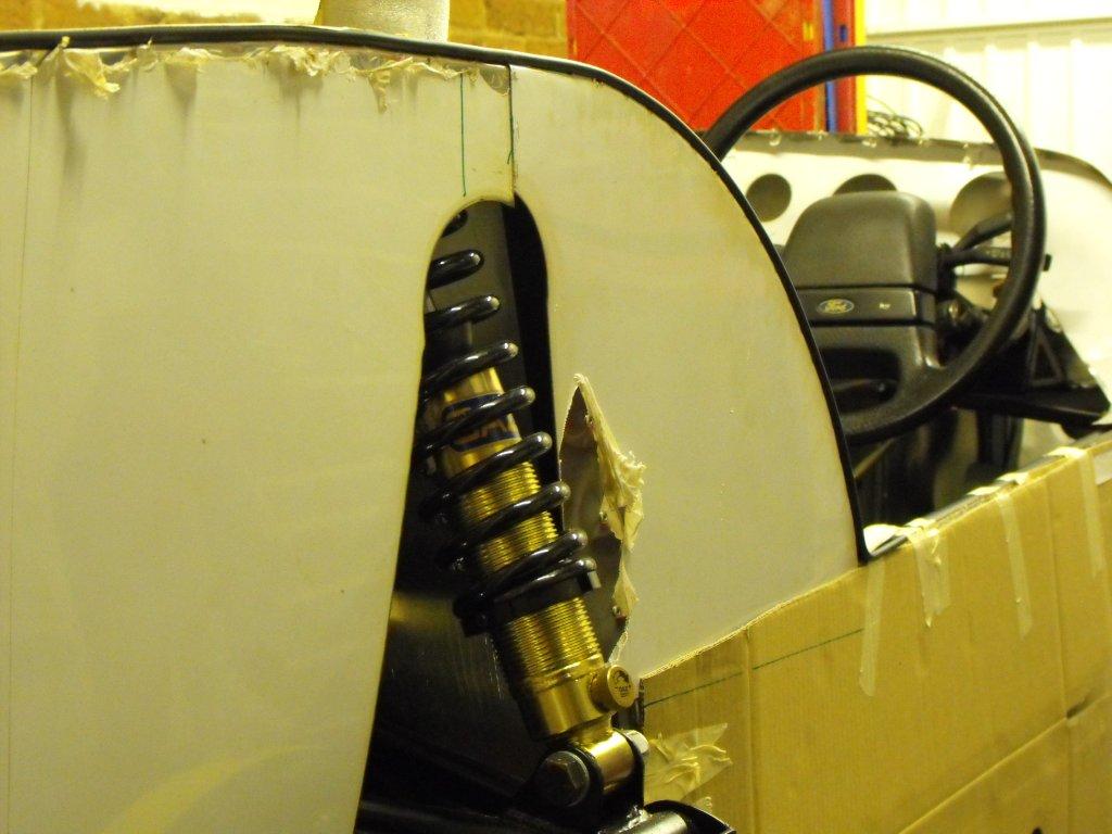
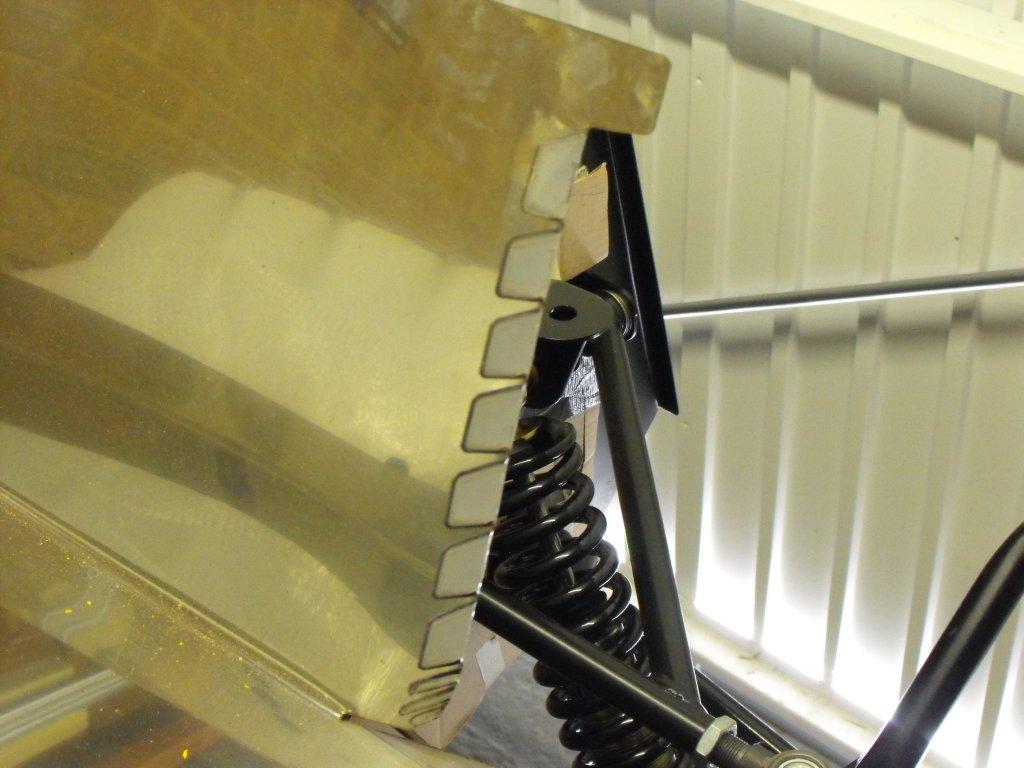
Then I tried to fit the rear panel to the chassis. As a temporary measure I used some self tappers in the upper shock mount/roll bar chassis mount before aligning the rear mounts which I used some M6 bolts until I ordered some rounded hex key bolts.
-
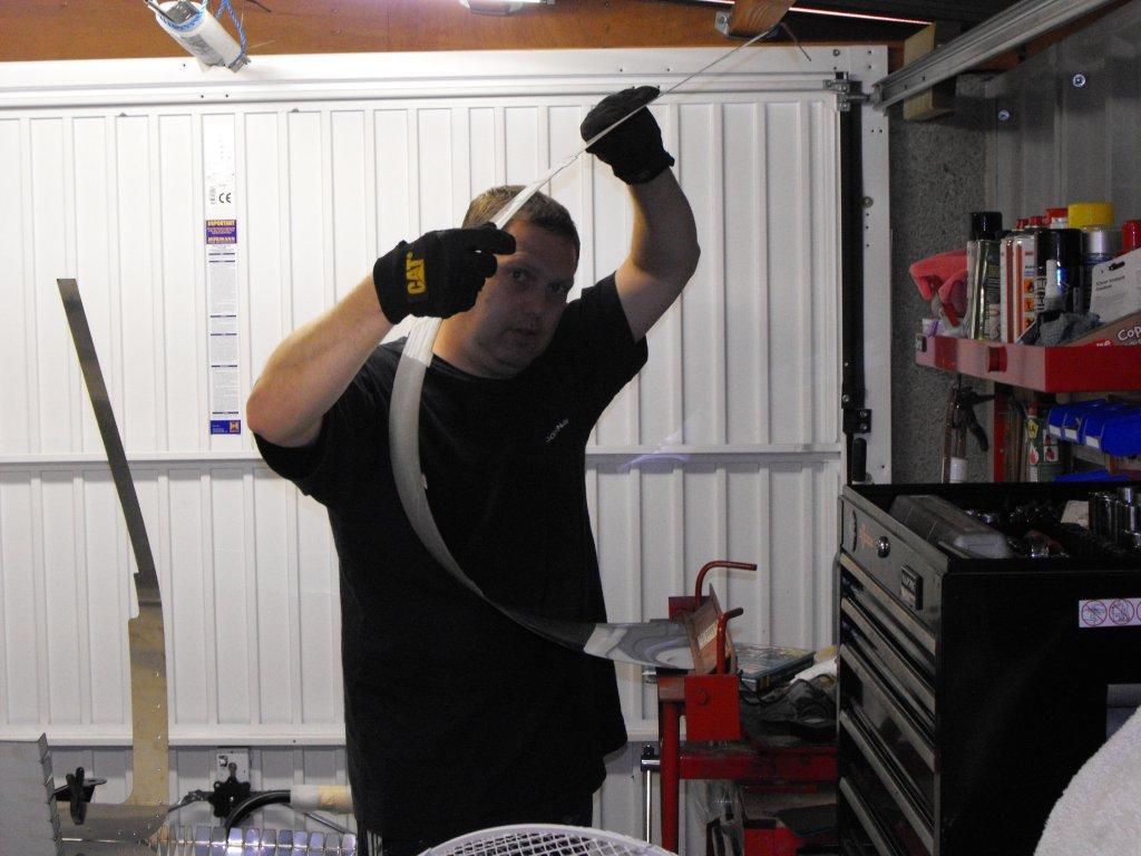
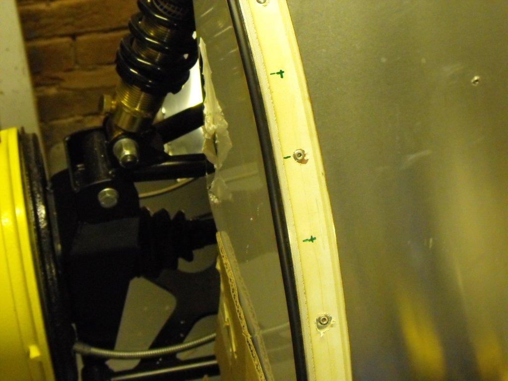
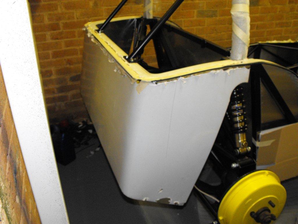
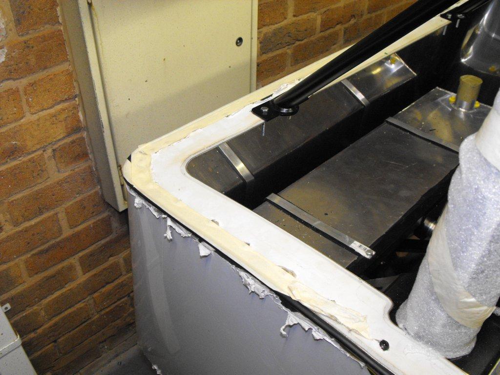
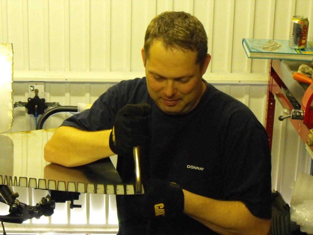
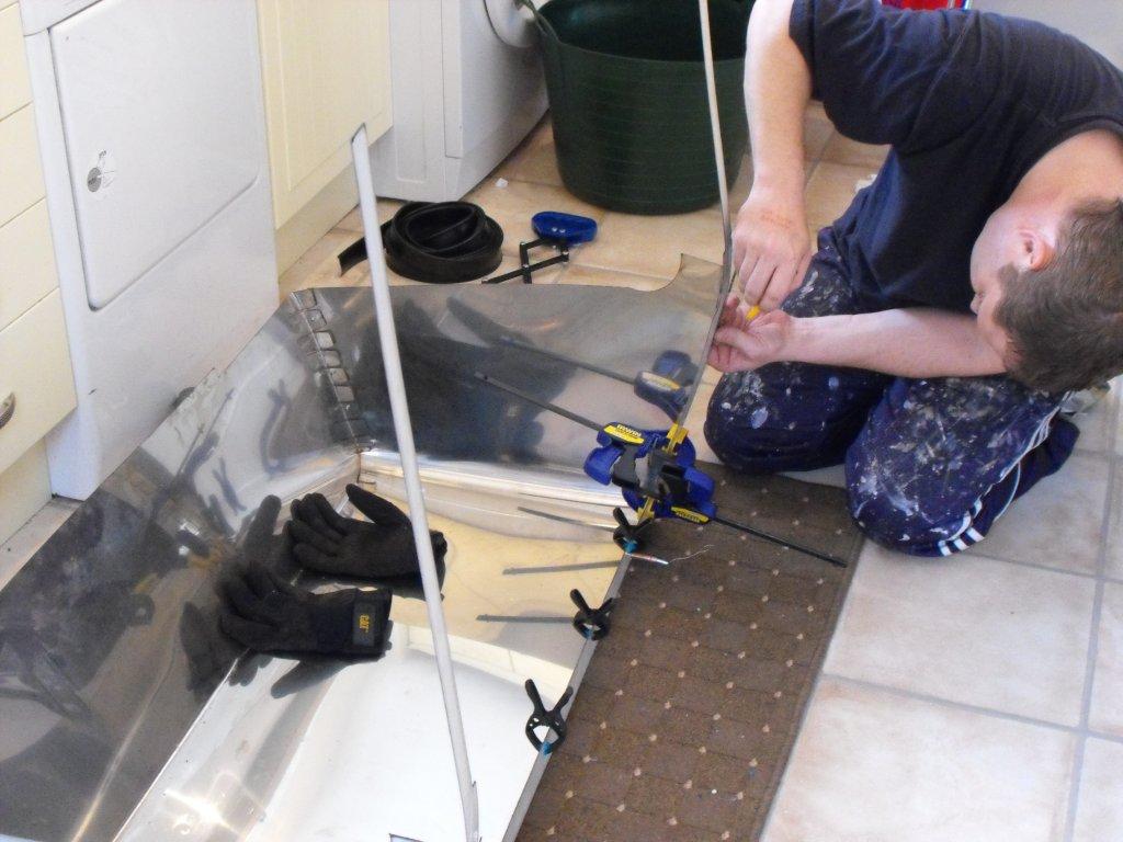
Next the rear panel. Most people are worried about this because you have to manually bend the panel to form perfect curves, it is much easier than expected. First job was to mark and drill the top piece, very easy with new cobalt drill bits. Then I had to bend the tabs on the lower edge and curved section (where your elbow sits when driving). I then place the top piece against the main panel and positioned it centrally, drilled a few holes and used clekos top hold them together. I chose to place inside because I knew I would get the holes evenly any gap would be filled with tadpole edging. Now into the kitchen on a rug to make the bends, gently role the panel, just pass where it needs to be fixed. It was easy but ideally a second pair of hands will help to clamp the panel before drilling and fixing with pop-rivets on the bottom piece and then top piece. Don't forget to use the tadpole edging. I always found it easier to glue the tadpole edging a little to ensure it does not move.
-
Good idea, and no need to buy spare ends for the rivnut tool, thanks Stephen.
-
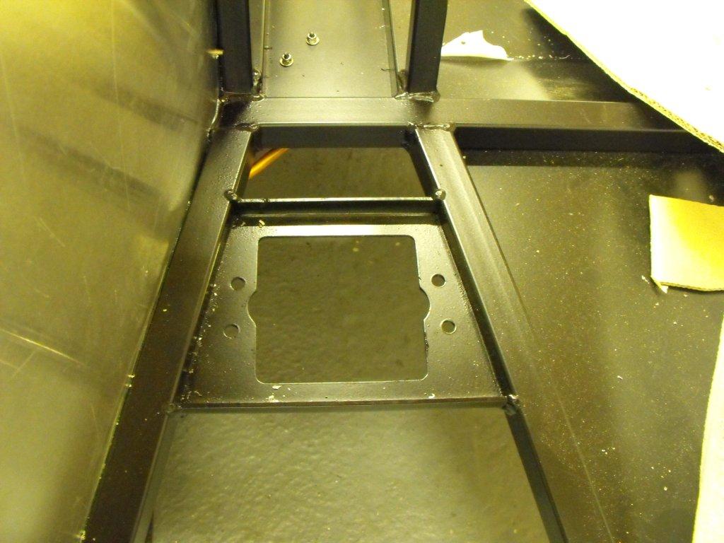
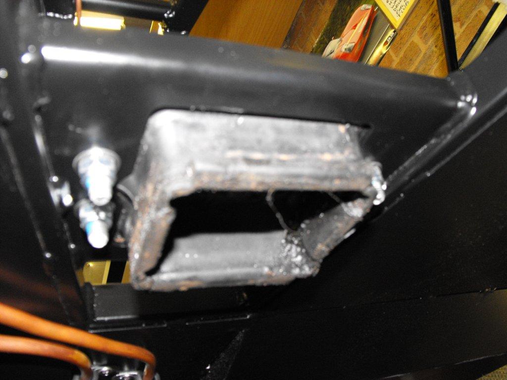
The gearbox mount was easy enough. I had to trim the old Sierra mount to fit the chassis. Then secure with four bolts, its not going no where.
-
Hi Stephen, I did use ally rivnuts but also used an earthing strap/wire direct to the rear earthing pointing, same one as the rear lights. One of those jobs, I will fix later. If I knew I was going to use so many rivnuts I would have purchased a decent heavy duty unit instead of the cheap tool similar as a normal pop rivet gun.
-
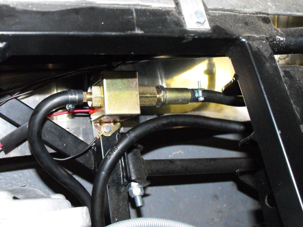
Thanks Ian, I have another in-line filter near the carbs, as soon as I have a fueling problem I will remove the facet filter.
-
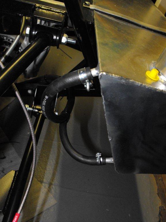
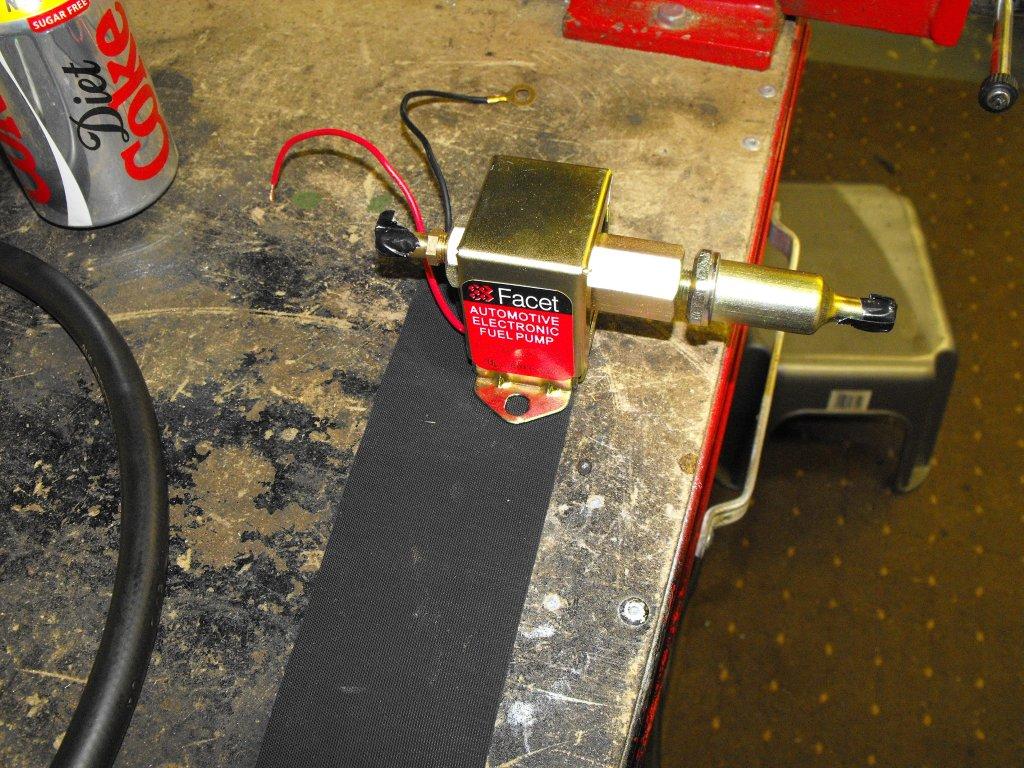
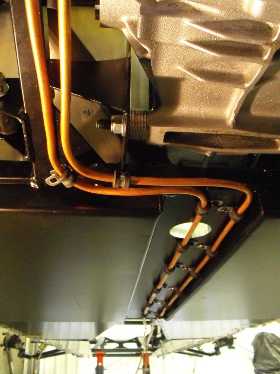
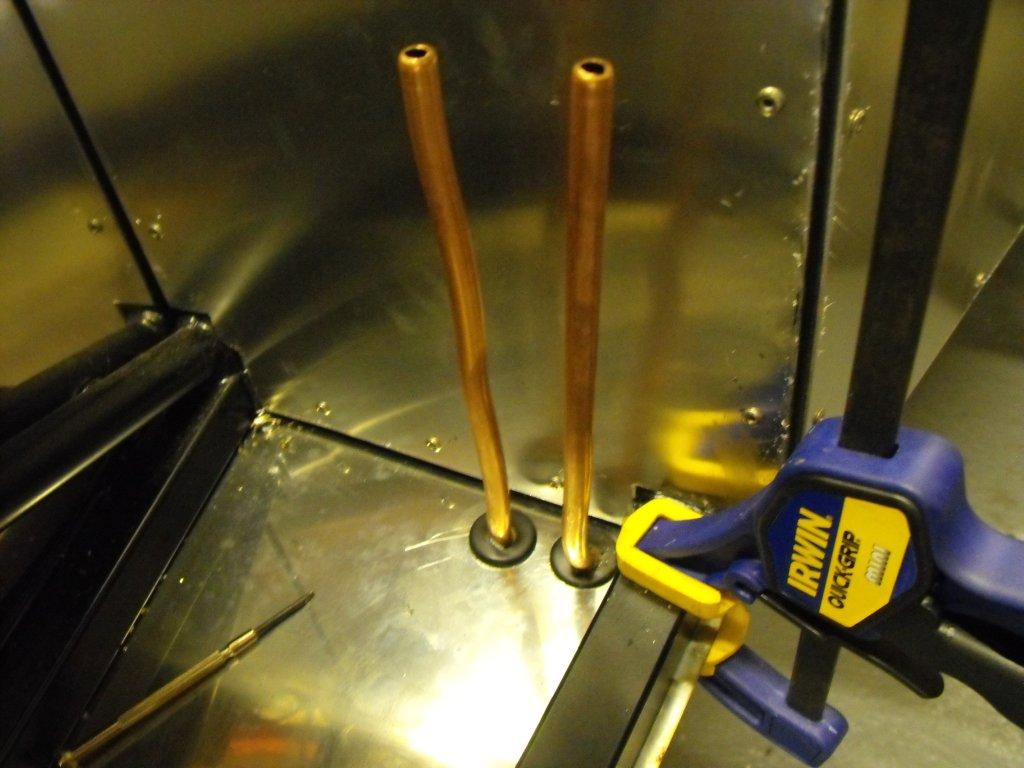
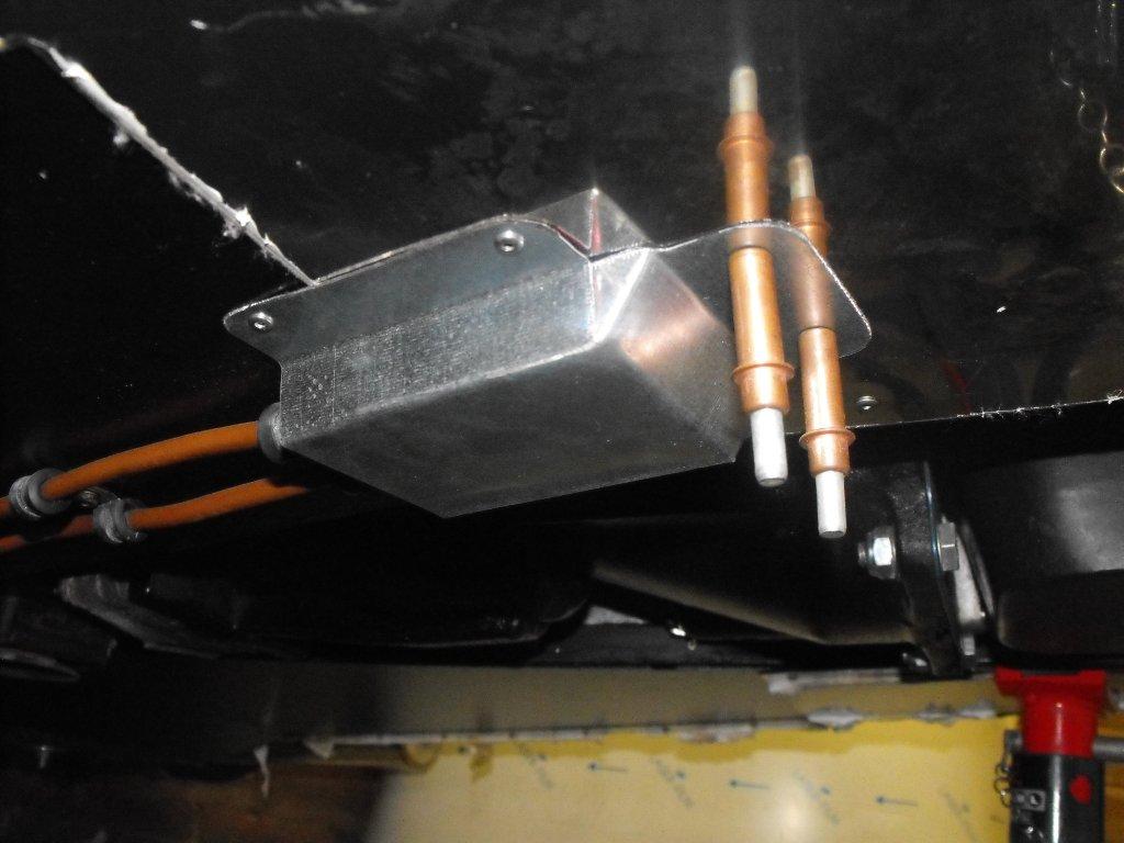
Before I fit too many panels I decided to fit the fuel pipe and fuel lines. I am not a fan of the GBS nylon pipes and I did not like the fuel pipes going down the propshaft tunnel so I decided on copper pipe and fuel hose to join the tank, pump and carbs. I used a short length of hose from the tank to the Facet fuel pump inline filter, and in preparation for a fuel return or leaking pipe I fitted a second line (currently blanked off) and the top hose is the tank breather fitted under the rear suspension top mount. I used rivnuts (What a great tool) to mount the fuel pump and a piece of rubber mat to keep the noise down. Now the contentious part fitting the fuel pipe underneath the vehicle between the lowered floor. Secure by stainless steel, rubber lined P clips. I made a little shied to protect the front part of the fuel pipe.
-
Excellent news, well done a great achievement.
-
Should be OK, air will find its way up to the highest point.