

bullfist
-
Posts
268 -
Joined
-
Last visited
-
Days Won
1
Content Type
Profiles
Forums
Events
Store
Community Map
Posts posted by bullfist
-
-
Sorry, we're away for that weekend. Cheers, -steve
-
I found this in a 50th year commemorative magazine insert.
Jack up one of the driving wheels. Engage top gear. Turn the free wheel back until compression is felt. Switch on. Give a flick forward and, if you are in luck, the engine will fire.
There is obviously an element of danger here, so I will have to say: do not try this!
-steve
-
In my build, I added a change-over switch to power the fuel-pump from ECU and permanent (ignition-switched)12v. Whenever I first powered the engine up, I had the switch on permanent 12v so that I knew that fuel was always available. The switch is centre-off so I have left it in-situ and use it as an immobiliser. I've also found that ignition-12v acts as a useful way to drain the fuel tank (hose into can). Obviously for safety, I never drive with the switch in ignition-12v.
When out, if I forget to turn the switch back from centre-off to ECU-12v, I also get the engine running for a few seconds then dying. This can be done a few times before it just wont fire because there is no pressurised fuel in the pipes.
It's only a suggestion, but rule out the obvious first (that's my mantra).
-steve
-
 1
1
-
-
Cannot add any more info unfortunately (couldn't see anything from underneath). If you cannot find your wiper motors, run three wires from motor to switch. Switch also needs +ve supply from ignition. Motor needs same and ground.
-steve
-
Very useful time - thanks dave (good to see your car in action!)
-steve
-
The wiper wires must have come out of the loom somewhere "above the gearbox". I'll have the car up on the ramp tomorrow (Dorset and Hants meet tomorrow). I'll have a look then, but apart from that I'm not sure (wired in the loom many years ago). IIRC the loom seemed to start from the steering, go to the transmission tunnel, where it split to the back and the front. Somewhere near the ECU and above the gearbox, the wiper wires must have come out.
-steve
-
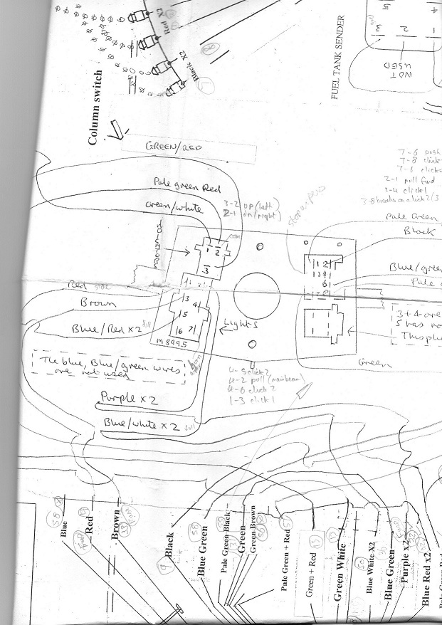
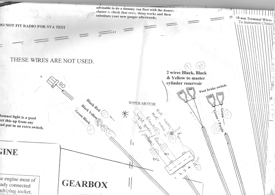
Have attached two scans of original wiring loom for wiper motor. From the technical bulletin mentioned earlier, it looks like you need a +ve supply to wiper motor pin 5 (green) and a ground to motor pin 3 (black). There are then three wires from motor to switch as follows:
Blue/Green from motor 1 to switch 6 (motor speed slow);
Pale green/Red from motor 2 to switch 8 (motor speed fast);
Green/Brown from motor 4 to switch 3 (park).
If you don't have these wires in the loom, just wire three new wires from switch to motor.
Switch has the three wires mentioned above and:
+ve supply (pale green/red - +ve supply switched on with ignition) to switch pin 7.
This should be all you need. I've typed this in quickly, so just make sure you've fused your circuits 'cos I could have made some mistakes. Also if anything's unclear please ask.
Connector can be female spades, I guess the original connecter latched, so that the connections would not fall out from vibration.
-steve

-
For my IVA, I had them on the body side in several places. But the tester wasn't at all happy with any location on the body and wanted them on the outer edges of the front wings (in his words, just how "Caterham's had them"). I didn't want them there but decided that if that's where he wanted them, then that's where I was going to put them - anything to get a pass. After six years, I've had no problem with them.
-steve
-
So where is the workshop? Is it one of the units directly behind the Esso garage, or is it a unit off to the side?
-steve
-
I'll have a look at the weekend -steve
-
Add me - I should be able to come over for a couple of hours in the morning - steve
-
Note from technical bulletin (March '05)
In the area of the wiring loom where the stalks are connected, there are three multiplug connectors. One has 3 wires to it, one has 6 wires to it and the other has 9 wires to it. In these instructions these plugs will be referred to as:
Plug X (3 wires)
Plug Y (6 wires)
Plug Z (9 wires)
1. The pale green / red wire on plug Z is shown as connected both to pin 2 of the indicator stalk and pin 8 of the wiper stalk
a. Connect pale green/red on plug z to pin 2of the indicator stalk ONLY. Do not make the connection to the wiper stalk.
b. Connect pale green / red on plug Y to pin 8 of the wiper stalk.
2. Connect wiper stalk pin 7 to green on plug z as shown in the original diagram.
3. Connect wiper stalk pin 6 to blue / green on plug y as shown in original diagram.
4. Connect wiper stalk pin 3 to green / brown on plug y. This is a new connection.
5. DO NOT make the connection from wiper stalk pin 1 to pale green / black as shown in original diagram.
6. DO NOT make the connection from wiper stalk pin 2 to Black as shown in original diagram.
Wiper motor
Connect the wiper plug motor as follows:
[[Drawing with 5 connectors in a line numbered from left to right (1 on left 5 on right), two locating tits at top, three locating tits at bottom]]
Connect blue / green wire to terminal 1 of wiper motor
Connect pale green / red wire to terminal 2 of the wiper motor
Connect green / brown wire to terminal 4 of the wiper motor
Connect green wire to terminal 5 of the wiper motor
Connect black wire to wiper motor body using a ring connector to one of the motor cover screws.
Terminal 3 is not used
===========
I guess from these you might need to see the original wiring diagram. I can try and scan parts of this at the weekend if needed - let me know.
-steve
-
1
-
-
The following circuits were excellent descriptions of how the super-spec wipers worked / parked (but don't use any of the pin-numbers / wire colours). If I remember, the switch operation was similar to "column switch" - always touching two adjacent contacts.
IIRC RH issued a bulletin revision on how to get the wipers to work this way. I'll see if I can find it.
-steve
-
How heavy is it?
-
Yes, I have a couple of 100w panels charging leisure (deep-cycle) batteries through a maplin solar-panel to battery charger. In the evening I run an inverter to power the TV - but if you have 12v LEDs, you wont need an inverter.
I had to upgrade one of the batteries to a large lorry battery so that on a hot sunny day like today it could store all the electric generated. It then runs the 40" TV for 4-5 hours in the evening.
As an initial test, I used old car batteries (old but not dead) because the inverter turns off before the battery is completely flat. Again with LEDs you wont get this option.
-steve
-
Link to item 118098 - now showing "unknown item".
In my opinion Wickes have an unbelievably shocking stock / order system (it's a long story) - they deserve to go out of business.
Even though Wickes is my nearest store - I'm going back to Homebase / B&Q
-steve
-
The black dot where the sun is in the picture is a novel feature.
-
Same with green flag too - newly qualified daughter - did a quotation for her, but seven days later when we took out the policy it had gone up slightly. Cheeky
-
Let's stick to the original suggestion "The Silver Plough" Pitton (BBC weather shows rain for Sunday up this way). 12 for 12.30?
-steve
-
Bob,
I tried to PM this, but it said you cannot receive any more messages!
=============================================
By the time Val's finished her dog-walking duties, it'll be 11.15-11.30am. Burlesdon Brickworks is reachable within an hour - unless it's dry and there's traffic (not uncommon in July).
So we can meet at the original pub. Or Val did suggest Whitchurch and - not the silk-mill - but maybe the gin distillery.
Cheers,
-steve -
We are free on Sunday - let us know time / location.
-Steve (+ Val)
-
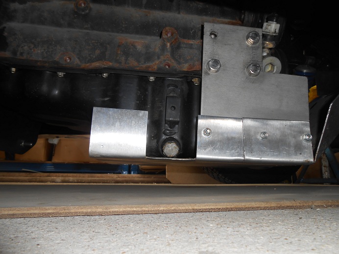
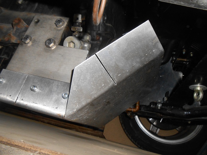
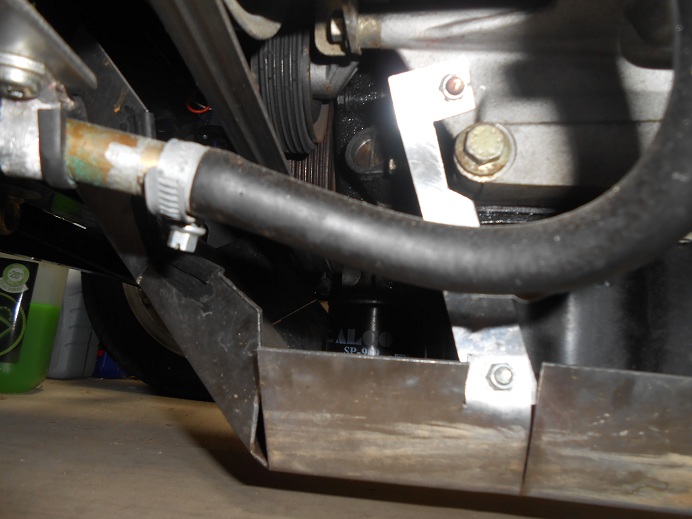
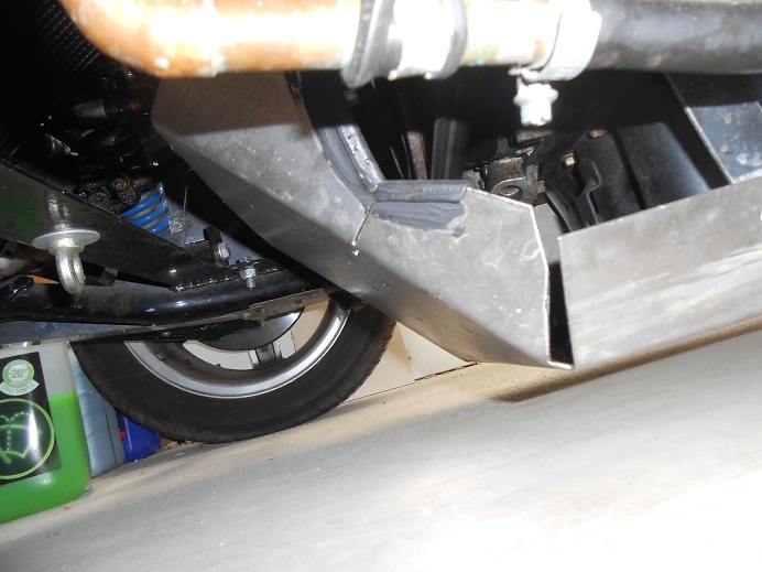
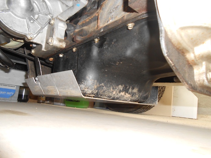
Pictures are deceiving - took them in a cramped garage - which had a sheet of 9mm plywood underneath the middle of the car (can be seen in first picture) and couldn't get a low enough angle from near-side.
Rear of plate is tight against sump - packed with rubber strip to stop vibrations - you can see a little of it from rear view. Doesn't wobble about as there are three fixing screws on off-side. It's good and tight.
As for photos - I had the same problem previously - the answer was that paid-up members can only post photos in certain forums.
-steve
-
Pictures in new chit-chat topic as I cannot attach to this one even though I've paid me subs.
-steve
-
Posted here because I cannot attach to original topic - even though I've paid me subs.
Pictures attached. First two are offside, next two are nearside, final one is rear (acts as a mud scoop as I reverse up the garden!).
Oh, and it looks like I used 2mm stainless plate (not 3mm).
-Steve
Robin Hood To A Gbs Zero
in Chit chat
Posted
From the limited pictures, it looks like there are sharp edges below headlamp, and the front indicators too far in from outer edges, which are IVA fails.
-steve