

Sparepart
 RHOCaR Member
-
Posts
351 -
Joined
-
Last visited
-
Days Won
14
Content Type
Profiles
Forums
Events
Store
Community Map
Posts posted by Sparepart
-
-
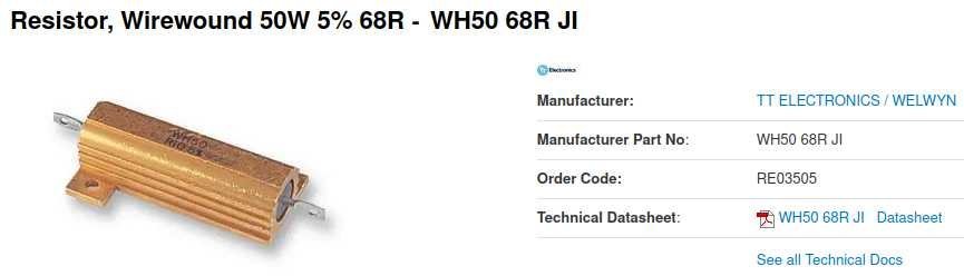
BTW. Any old type of resistor won't do. It must be able to operate without overheating and burning out. The 2.2 watt ignition light gets quite warm, eventually can burn out and stop the alternator charging. It is not expensive to buy a resistor that will more than cope with the power. I attach photo of an example below, only costs around 3 quids and should last until the end of the universe. You would need one at whatever ohms you are after of course not necessarily the one shown.

-
I have recently been investigating this subject due to having destroyed an alternator trying to change the brushes,.... we don't talk about this. However, here is what I think I believe is relevent to this thread. The connections on the alternator are a group of three spade terminals in a line, two large and one smaller. The two large terminals are connected together, that is they are essentially one terminal, check this out with your meter. On my car they are both connected to the same heavy duty cable going directly to the positive terminal on the battery. The small terminal is connected to the alternator regulator circuit, the circuit that controls the current feed to the field coils which regulates the output from the alternator (on the big terminals). When the alternator is generating power, it uses the generated power to feed the field coils under control of the regulator. So it's a chicken and egg situation. If the alternator is not generating power it can't engergize the field coils. This is the situation when the engine is first starting up. A small current is needed by the regulator in order to slightly energize the field coils to generate a tiny current that is then fed back into the coils etc. until the process builds up to the large current output produced by the alternator. This small current of course comes from the battery. It is convenient to use the resistance of the filament in an incandesant light bulb to allow only a small current to the regulator because as soon as the alternator starts to generate a greater current at 12 volts, no current will flow to/from the battery to the regulator and the light bulb will go out. We call this bulb the "ignition light". On the Sierra donor, this bulb is rated at 2.2 watt. At 12 volts this means that the current flowing to the regulator at startup is 183 milliamps, and implies that the bulb provides a resistance of 66 ohms. It's important not to feed too much current to the regulator, it might cause harm, so any lower resistance in this circuit should be avoided. Higher resistance is safe as long as enough current flows to get enough initial field in the field coils. Replacing the Ignition Light with an LED or any high resistance device/circuit usually prevents enough current reaching the regulator, accordingly a resistance can be introduced IN PARALLEL, remember the formula 1/R = 1/r1 + 1/r2, such that the total resistance is reduced towards the nominal above.
-
I still have EXMO build DVDs (Copies of the VHS), Message me to discuss logistics if you want copies.
-
I echo IanS .... I typed the below before I read his reply....duh!.
In the above you refer to "bolts" and "studs" I'm not clear what you have, but under the car if you see a bolt head for a bolt that goes up through the floor and into the seat, and you are worried about the nut at the end of the bolt not being fixed to the frame, then this will be obvious as soon as you undo the bolt. If it's not fixed then it may turn and prevent the bolt from unloosening. If its held in some form of channel then as soon as a noticable amount of thread appears as you undo the bolt you can try pushing up on the bolt to see if the nut comes out of a channel in the frame. However if you have a "stud" coming out of the bottom of the seat you will see a thread coming through the floor under the car and a nut to undo. This will not be a problem because if you can get the nut off you will still have the stud sticking out of the bottom of the seat when you lift it out.
-
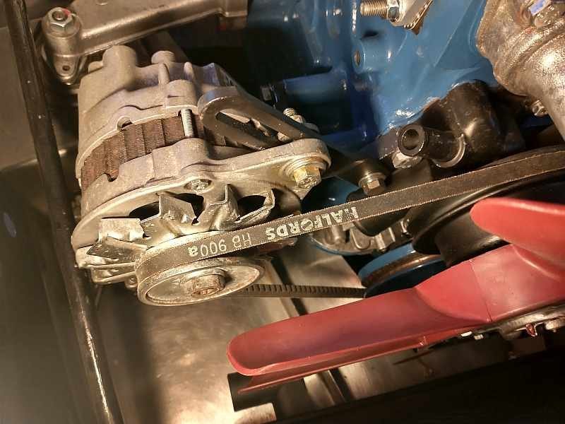
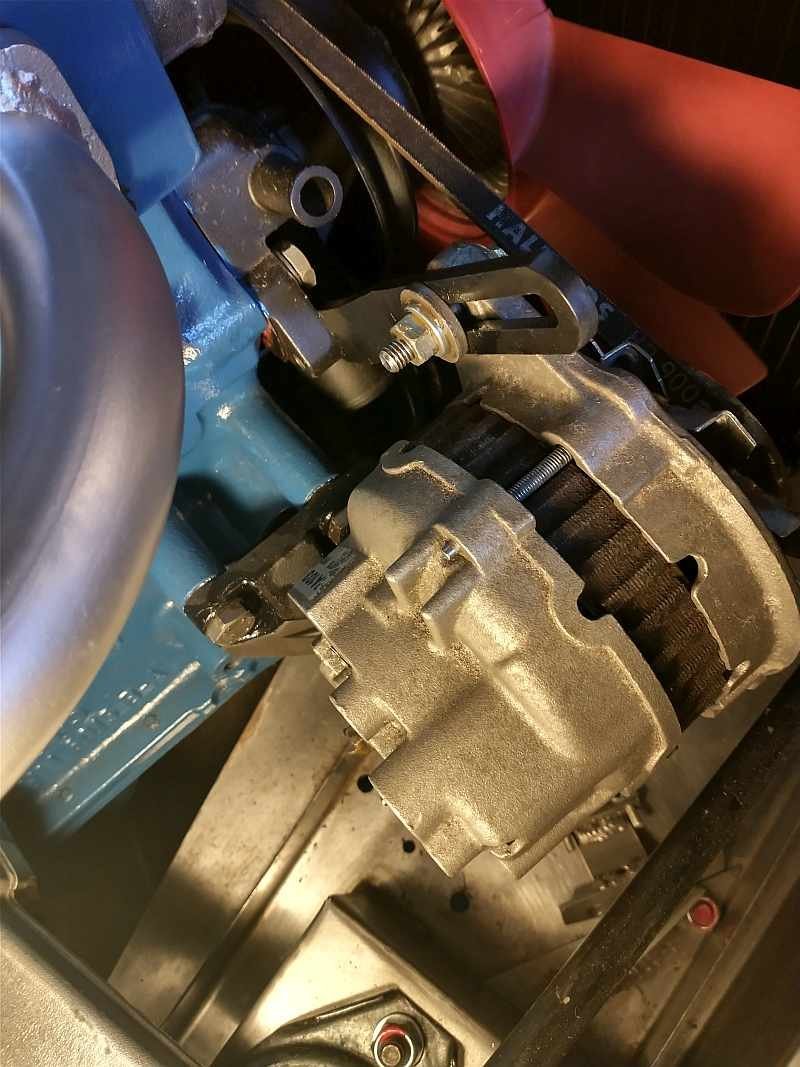
Here are a couple of shots of the alternator arm on my car. The Engine end of the arm is fixed by a bolt that threads into the water pump, M8 I think.
-
Sorry if I have not been clear in my description. I have rebuilt as is, i.e. no modifications to the choke mechanism. From the manual, I performed the 56 steps to disassemble into all the parts, then followed the 81 (yes 81) steps to rebuild using the service kit parts and feeler gauge where needed. As you can see from the final pictures in the rebuild series everything is back together including the stepper motor. It's waiting to be fitted when my feet don't cold in the garage. There are still 28 steps, under "Adjustments and Tuning" that need to be carried out when the engine is running and cold then hot. I have seen this as a "challenge" rather than what I would advise anyone to do. When you consider the complexity of this carb and it's dependence on the ESC2 ignition system I am willing to ditch it all and fit a simpler carb and new ignition system if it doesn't work out.... it's just because it was on the Sierra when I took it apart and I thought I would try and keep it .... you know reuse, recycle etc.

-
Strangely, I spent last winter rebuilding this carb, for my car, bought the rebuild kit, stripped down, rebuilt, its waiting to be installed this spring. I have detailed photos of the strip and rebuild. I have loaded them on to a OneDrive and set them up to be shared via a link for a browser of your choice. I am placing the link below, I am sure you will let me know if it doesn't work. I also have a digital copy of a chapter from a Weber manual that I used..... however I won't share it here for fear of copyright issues.
https://1drv.ms/f/c/13a2e334f3ad6ca6/EoE7NxHD1XROsY__3Bn75jMBEPg22cZbdn8hwRESyBGsHQ?e=Ijwqpy
-
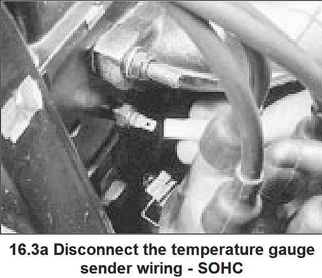
Here is a poor quality rip from the manual, you can see where it fits in relationship to the distributor. BTW - this sensor is the one that is used for the water temperature gauge on the dashboard. In the unlikely event that your engine is using the ESC2 electronic ignition then there is another temperature sensor on the inlet manifold, used by the module to control the choke stepper motor and engine advance.
-
The answer to your second question is yes, if you scrap a vehicle the V5 must be handed in at the ATF (Authorized Treatment Facility) you only keep the yellow part of the V5 as for a sale or transfer. This is all covered in the official documentation at https://www.gov.uk/scrapped-and-written-off-vehicles. If a registered vehicle is not scrapped or written off then someone must either pay duty or have a SORN in place. Given this, I can't see how the actual donor V5 can be part of registering a kit car, although of course a photo copy or scan could be retained by you.
-
I attach below a pdf that has a colour diagram of the lighting circuits. The steering column switch shows up as items 35 and 36 which are housed in the same unit and share contacts. So looking at this we can answer your questions about contacts as follows:-
54. Live via Fuse 9 from ignition switch posn 2 and 3
30. Live direct from battery
15. Live un-fused power from the ignition switch posn 2 and 3
31.- Can't see this on the column switch (35/36) it is the earth connection on the indicator flasher relay. If the one you see on the column switch has brown wire the its probably an earth.
56a. Feeds fuses 14 and 15, Main beam (also driving lights relay which you most likely dont have)
56b. Feeds fuses 16 and 17, Dip beam (possibly a dip beam relay which you most likey dont have)
55. Think that might be the horn.
58. Feeds fuses 18 and 19, Side lights, number plate light etc.H is power from the Hazard warning swich, on top of column.
L. and R. are the Left and Right power to the LHS and RHS indicator bulbs from the flasher relay via pin 49a.The frantic clicking of the flasher unit is most likely either a bad bulb or bad earth to the bulbs. The flasher unit uses the current flowing through it to heat a bi metal strip, that then breaks the contact until it cools down and then makes contact again etc, it is wired in parallel to the flasher bulbs, and has its own earth (see diagram) so if the bulb circuit goes to hight resistance, more current flows through the flasher and it heats up quicker and operates more often.
-
Looks like they are screwed into a piece of threaded tube that crudely welded to the frame. There is corosion around the tube base and it looks like moisture could get in there. So most likely the end of the thread at the base of the tube has rusted and expanded so that now it has to cut a thread through the rust as it unscrewed. I would give both ends a dose of wd40 and then slowly increase the amount unscrewed by turning till it stops then screwing back in a bit, then out a bit more, then in again etc until a thread is cut thruough the rusty bit.
-
Also you might try starting and running the engine with the alternator disconnected.
-
Maybe you have checked out the following thread there is a long list of things to look at and a final resolution of a problem very much like yours.
https://www.fordownersclub.com/forums/topic/126981-air-con-clutch-not-engaging-pressure-relay-okay/
-
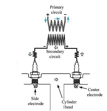
I found this topic very interesting, so did a bit of digging and soon found the reason. When the same coil is used to generate the two sparks the plugs are wired in series with the secondary coil between the two plugs. The current flow for the spark starts in the engine block, travels from the outer part of one plug to the central electrode, then through the secondary winding to the central electrode of the other plug and back to the block via the outer part of the plug. This difference in electron flow through each plug means that the erosion behaviour in each is different, one plug has +ve central electrode other has -ve central electrode, so the central electrode metal alloy is different. The diagram below makes it all clear.
-
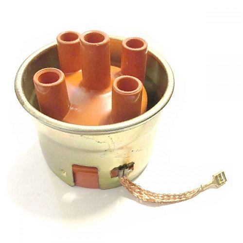
In the Sierra donor car that I used, the ignition system had two things not mentioned so far in this thread. I think both were to try and prevent noise on the AM/FM radio and also protect the early form of electronic ignition. The first was a galvanised steel shroud fitted tightly around the top of the distributor, where the rotor arm whizzes around, the shroud had/has a very visible earth strap to the main body of the distributor. This is a ford part, but it's somewhere in one of my bits piles, and I can't find any references to it on the web, I'll try and find it. I attach a photo of one from a different distributor so you can see what I mean. Anyway I assume that this shroud helps remove some of the EMI associated with the small sparks that jump the gap between the rotor arm and the pick up pegs in the cap. I would think that this gap has to be significant to allow for a worn distributor shaft. The second device is not for EMI, it serves to remove voltage spikes in the loom caused by the primary winding of the ignition coil. This takes the form of a capacitor connected between the +ve connection on the coil and earth. The Ford part number on mine is 71HM-12A 019-A2A it is rated at 2.2 micro farad 110v.

-
I have a cunning plan. Would you go along with the idea of concentrating on each of the bits of kit in turn and in isolation?. The aim would be to deduce what each device is capable of, what function each of the connectors serves, and whether or not each device is working correctly. Then armed with this knowledge we should be able to work out a wiring diagram to achieve what you want to do, within the limits of the devices of course. This would mean you doing all sorts of tests using a multi-meter and reporting the results, which may in turn suggest further tests. I don't know how "electrics" savvy you are, so you might have to put up with what might seem patronizing questions occasionally. If you'd like to give it a go, then the first question is simple, will you list all the devices that you believe are involved in this project, I mean everything that has wires going to it or connectors on, for example "2 actuators, 1 push button, 1 key fob", don't include anything that you have added, as they might be red herrings. Oh and yes I assume you have a multi-meter, capable of measuring DC voltage in the 0-20V range and resistance in the 0-2K ohm range, if it also has an audible continuity function so much the better.
-
First off, like Nelmo says we don't see many questions like this. However there's no harm in asking the questions. If possible do you have any details regarding the manufacturer and model of the bits, any clues like part numbers or names on the bits ?... I sort of assume you do since you say that you have been watching "everything on line" ... so any links to what you have watched?. One thing I notice on one of the hand crafted circuit diagram is that the actuaters appear to have one lead connected to earth. I think you will find that the two wires to the actuator are meant to be used as reverse polarity inputs. That is to say current through in one direction will lock and then reverse direction for unlock. So in the diagram showing a lead to earth the actuators are only going to operate to lock or unlock but not both, and judging by the written comment it looks like they only unlock.
-
I am assuming that the pictures are looking down on the header tank of the radiator ?, personally I hve not seen one like this before. Anyway, if it is the header tank then you have noticed the small outlet/inlet on the RHS. If there is no filler with pressure cap on the unseen part of the header, then this small pipe is probably where a seperate header tank is connected. It would be somewhere in the engine bay mounted higher than the higest point of the engine water jacket. It's probably plastic and has a pressure cap.
-
I have a suggestion. Find the engine code of youre blacktop and then search again for info using the code. You might even find some information by searching the magnificent archives of this site. For example, your next question is "Where do I find the engine code?" and guess what, we already have a thread here about this:-
https://www.rhocar.org/index.php?/forums/topic/32675-zetec-blacktop-engine-number/
Then you might pick up info on the web such as:-
I don't know, but perhaps some spare part sites specify applicability by engine code. Hope this helps.
-
Thanks for that. The £13 KA master cylinder arrived. It's for a MK2 KA. It looks like its not a repairable item, no circlip holding the piston in, also it features one of those tiny trapped ball bearings that is probably some form of pressure relief. The diameter of the ring on the mounting surface is quite large. On the plus side the two output ports would be on the side away from the exhaust manifold. The diameter of the bore is not obvious. Googling away for more info it appears that on the KA the two outlets are used for diagonally opposed brakes, and there are two possible bores 20 and 21 mm. So on the face of it this might not be the best candidate. I am going to continue with trying to fit it, however am busy web surfing for other possibilities, preferable with 19 mm bore.
-
I'm rebuilding the Exmo after 17 years under a tarp. I'm re fitting the brake servo and master cylinder, the ones from the donor Sierra. I'd forgotten how close to the exhaust manifold it all gets. I stripped the master cylinder to find a sorry state of gunge and corrosion. The bore is so-so but the rubbers and springs are shot. I could buy a repair kit, however I suspect it would not last long. Getting a whole new master cylinder (Lucas/Girling Part No. 74066315) is prooving elusive. So I am going to try fitting a Ford KA master cylinder without a servo. Searching our archives here there are plenty of mentions of this having been done, however no specific information with part numbers and instructions. Does anyone here have such information that they are willing/able to share ?...... I have bought a cheap used "KA master cylinder" on eBay, (waiting for delivery), and will soon start trying to make it fit.
-
The answer to your question is NO, you don't always need a donor car. IMHO it just depends on how much money you are prepared to spend. Do that first. At one end of the scale buy a complete kit from Caterham, with little mechanical knowledge and a few free weekends you can be on the road in no time. On the other end buy Ron Champion's book https://www.amazon.co.uk/Build-Your-Sports-Little-£250/dp/0854299769 and learn how to do the mechanicals/design and meet IVA requirements and get parts from many donor cars and in SEVERAL years you might be on the road if you have the tenacity to complete your mission. In between these two extremes, just Google "UK kit car manufacturers" and you will see many choices try https://www.totalkitcar.com/uk/uk-manufacturers/. Try and look at the build manual of something you like, see if you feel it's within your skills, think about the cost, and make your choice. Good luck.
-
Just to be pedantic the part number is QCC1585.
-
My personal experience is with the Exmo kit. You ditch the Sierra expansion tank and use the radiator from a Cortina. This radiator is mounted vertically such that the level of coolant in the header tank is high enough to be the highest point in the cooling system while still leaving an air space for expansion. I just used the pressure cap that was originally on the Sierra expansion tank. This is a 2 litre Pinto. Overfill the radiator, i.e. to the top. Run engine hard to get to high temp, expansion causes overflow which I just let drain away. After that no more overflow and you can see the space needed for expansion. In my case it was say about 20 mm above the top of the core and did not go lower. I could have added an overflow pipe and collector bottle but I never see any more coolant come out. I just check that the level is that same 20mm above the core from time to time. In case it is of interest. I list the temp and pressure ratings for the Sierra below. Not sure waht happened in 1987 probably the fuel injection.
Thermostat
Nominal temperature rating (fully open):
SOHC models . . . . . . . . . . . . . . . . . . . . . 88ºC (190º F)
CVH models . . . . . . . . . . . . . . . . . . . . . . 100ºC (212ºF)
DOHC models . . . . . . . . . . . . . .. . . . . . . 102ºC (216ºF)
Opening temperature:
SOHC models . . . . . . . . . . . . . . . . . . . . . 85 to 89ºC (185 to 192ºF)
CVH models . . . . . . . .. . . . . . . . . . . . . . . 88ºC (190ºF)
CVH (R6A type) model. . . . . . . . . . . . . . . 85 to 89ºC (185 to 192ºF)
DOHC models . . . . . . . . . . . . . . . . . . . . . 85 to 89ºC (185 to 192ºF)
Expansion tank cap opening pressure
SOHC models:
Up to 1987 . . .. . . . . . . . . . . . . . . . . . . . . 0.85 to 1.1 bar (12 to 16 lbf/in2)
From 1987 . . . . . . . . . . . . . . . . . . . . . . . 1.0 to 1.25 bar (15 to 18 lbf/in2)
CVH models . . . . . . . . . . . . . . . . . . . . . . 1.0 to 1.25 bar (15 to 18 lbf/in2)
DOHC models . . . . . . . . . . . . . . . . . . . . . 1.0 to 1.4 bar (15 to 20 lbf/in2)
Help me out here
in General Discussions
Posted
I looked at the links, reasonable enough. A "new adult" usually has a lot going on and a busy life etc. You know him better than me (obviously), first take a step back and consider whether or not to get him started on something that will take up a lot of his time. If he is rich, then of course a top price kit from Caterham can be built in several weekends with access to a decent garage and tools. Bit like buying a Lego kit to build a Star Wars object, buy the kit, follow a plan, and hey presto kit built and the itch to put it together and play with it is truly scratched, now move on to something completely different like Fly Fishing ..... you know what young adults can be like. If he is not rich, then kits that leave more for the builder to figure out and understand will take up more time and real concentration on the engineering principles involved in puting it all together. The danger is that he will run out of steam and after a year we will see the bits and pieces of his partialy completed project for sale on eBay. If you think that it is something you would like to see him doing then I would advise that finding web links to advice sites is useful but he can easily do this on his smartphone while eating his cornflakes, no, I would advise you to have a bet with him that he can't put a kit car together, a personal challenge from his aunt. If he accepts the challenge then job done, he will do the rest, if he doesn't then you will know that he is not really serious about it. OOps here I go again, on a soap box......too much advice probably.