AndyW
 RHOCaR Member
-
Posts
395 -
Joined
-
Last visited
-
Days Won
6
2 Followers


Recent Profile Visitors
66,789 profile views

.thumb.jpeg.421a94eb7659e4981873a5021583a657.jpeg)


AndyW's Achievements
")
Wheely good builder! (4/6)
62
Reputation
-
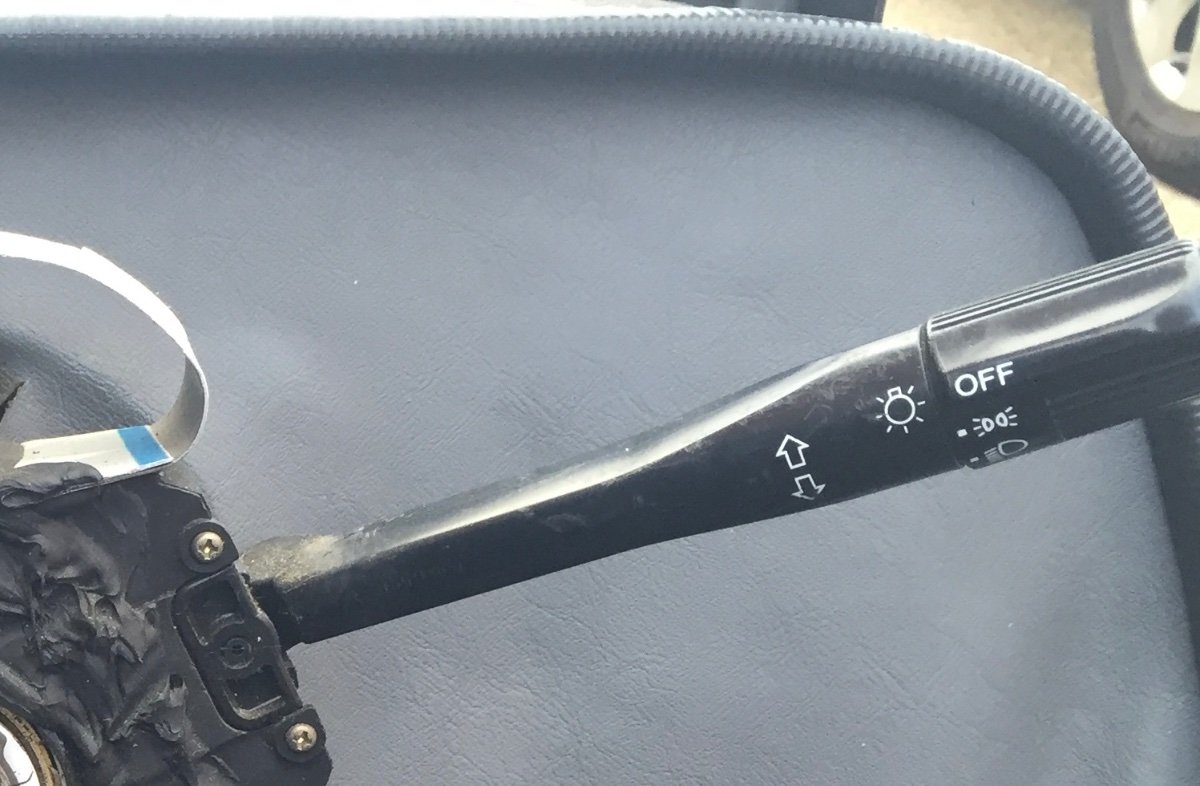
This is the RH supplied Rover column light switch if it matches yours? When you’ve checked all the fuses for the lights are ok, then check the wiring at this switch. No loom connector was supplied so you had to use small female connectors to wire directly to the exposed pins on the switch base. Mine were not very secure and on occasions came off or moved and touched each other. There are 2 groups of pins. On my car they were wired as follows: 3 pins for 12v power from flasher relay, to left & right indicators 6 pins for lights: 1: 12v for sides 2: to main beam 3: to sidelights 4 & 6: 12v for headlights 5: to dip beam Check yours are all intact.

-
In common uk wiring and the original part Ford loom supplied with the Superspec, blue/red is used for dipped beam, and blue/white for main beam, between the switch and the bulbs. But you said your front and rear side lights weren’t working. Those are a separate circuit to the headlights. They should be a solid colour red wire feeding all of those and the instrument illumination. Are you still using the original Rover column stalk switch for lighting?
-
If your car still has the original RH wiring loom, the side lights were all powered by a permanent live from the light stalk, which went to a 10a fuse and then out to all lights through red wires. Hopefully straight forward to track down.
-
Yes the injectors are 12v, powered through the MEMS ECU from its 12v relay supply. The ECU earths them to control the injector pulse length. So ECU gets 12v power to pin 28 (brown/pink) from ignition relay. Then I *think* it is passed inside the ECU to the injectors as a constant 12v but I'm not sure of the wiring connections or colours. The injector pulses are then controlled by the ECU earthing... Injector 1 to pin 24 (yellow/blue) Injector 2 to pin 23 (yellow/green) Injector 3 to pin 26 (yellow/white) Injector 4 to pin 1 (yellow/black) If you're only seeing 4.5v going to injectors then that doesn't seem right. 5v is what the ECU uses for the sensors. So have you got the correct wire? And did you have ignition turned on to power the relay to pin 28? Andy
-
It might be a bit late now you’ve started painting, but I had good results with Frosts Extreme Chassis Paint in satin black. I used it to brush paint my wishbones and hubs 3 years ago and still looks good now. I was put off using hammerite smooth as reviews suggested it chipped easily and came off in flakes.
-
That wouldn’t work as there is only one wire from the sender to the gauge. There are 3 possible fixes mentioned in early forum posts: 1) rejig/bend the float arm so it operates on the other side of the sender, 2) invert the potentiometer on the sender so the float arm swipes the other way, or 3) unsolder the signal wire on the potentiometer and solder it onto the end of the coil.
-
When you replaced the fuel pump, was it just the pump, or did you replace the whole sender, float & pump? If it was the whole in-tank unit, then It’s likely your gauge is now reading back to front. As originally supplied the Superspec fuel gauge read in reverse - full when empty and vise versa. You had to swap the wires on the potentiometer to get the gauge to read correctly. Although there was an electronic Spiyda module you could buy to correct the calibration. Don’t know if the previous owner might have fitted one of those? It’s a bit difficult to tell from your photo, but the tank looks near empty to me. If it was 3/4 full you’d clearly see the petrol level a couple of inches from the top if you removed the sender unit. As Al says, you need to check your filler and vent pipes on the fuel tank and make sure there are no kinks or restrictions. I can fill my Superspec at pretty much normal speed, just have to slow down when it’s nearly full. I regularly put in 30-35litres and drive it for 200 plus miles until it gets down to a 1/4 again. The original tank takes 42 litres.
-
I had slow cranking on my Superspec with my original tired battery. It was helped by improving and cleaning all the earths. Best to have 3-way direct earth cables or straps - battery neg to starter mounting bolt, battery neg to chassis, and engine block to chassis.
-
And if he wants to look at lots of different kit cars, the Kit Car show is on at Malvern this weekend. Worth a look around if he can get to it.
-
Good news on the fuel pump. On my car, the tps wiring loom connector has: Term 1 (+) is the supply. yellow/purple goes to ECU pin 9. With ign on should be 5v Term 2 (o/p) is the wipe output signal. yellow/green goes to pin 8. With ign on and throttle closed should be 0.6v, throttle fully open should be 4.3v. Change should be progressive between. ECU idle position is determined by the 0.6v closed reading. Term 3 (-) is black/pink and goes to ECU sensors earth on pin 30 So your wiring seems ok. If you don’t get those voltages then the potentiometer may be suspect. My battery is a Varta C6 Silver 52Ah which is perfectly fine for cranking and starting. I had terrible hot cranking problems with my previous battery until I determined it was duff and replaced it.
-
The fuel pressure regulator on the end of the fuel rail operates at 2.3-3bar. If you remove the return hose from it, and turn the ignition on to get the initial 1 sec pump priming, then fuel should come out of the regulator (put a container underneath!). And definitely when you crank the engine. You should be able to hear the fuel pump whirring. If no whirr or no fuel comes out then the pump isn’t working. Make sure you tightly clamp the fuel hose afterwards. If you get fuel out ok, then remove spark plugs and crank again. You will get a strong smell of petrol if the injectors are working ok. However this all assumes your crank sensor is now working correctly.
-
I agree with Al that your Crank Position Sensor looks very dodgy. The CPS trace for my engine is like Al's, on and a completely solid line as soon as the engine is cranked until turned off. The fact that yours turns on and off might indicate a problem. The CPS is fundamental to the engine running. Without a cranking signal MEMS won't know the engine is turning and won't operate the coil or injectors. From my notes, here are some things to check on the CPS: - disconnect the plug and check resistance across the 2 sensor terminals, should be 1260-1540 ohms - check the plug and wiring is intact, and all connections are making good contact - check the sensor is correctly fitted over the flywheel. It's held with 2 bolts and there should be a spacer underneath to give the correct distance away from the 34 reluctor poles on the flywheel - the 2 core cable should be connected to the engine loom with a screened and earthed cable to prevent interference - the wires should connect blue +ve to MEMS pin 31 and white -ve to pin 32 (my engine wiring colours) - the blue wire should show 5v with ignition on, and then drop to 3v when cranking
-
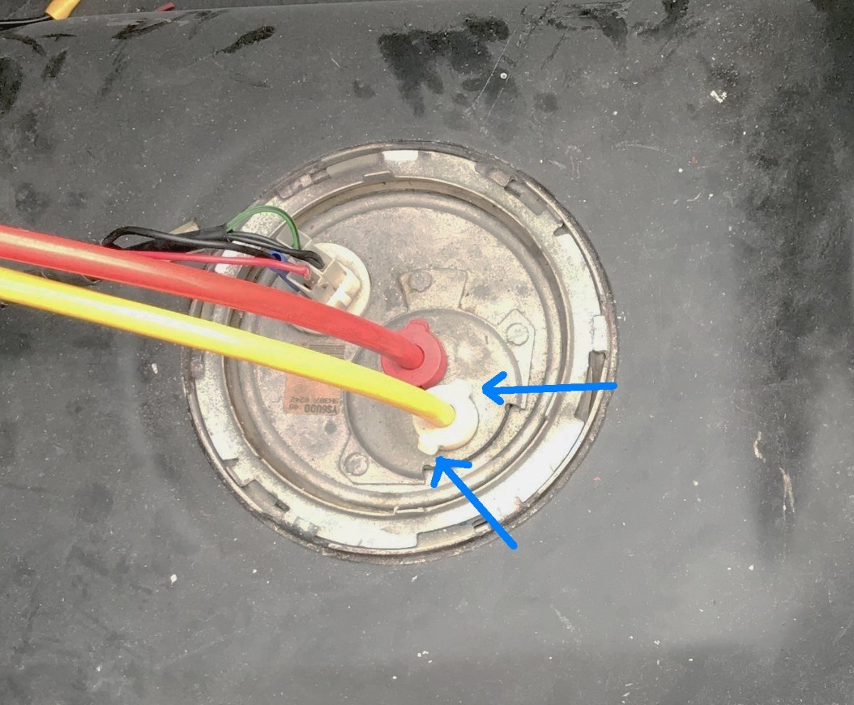
Yes I should have explained better. My photo shows how some Superspecs (not mine) have the fuel hoses simply pushed into the pump connectors. My car actually has the proper elbows as Al describes, though I didn’t have a clear photo to show them. I would think the plastic elbows give a more secure and rigid connection, and also have the added advantage that they reduce the height of the hoses curving above the tank and hence the risk of kinking the fuel hoses with boot boxes or anything else on top.
-
I replaced the fuel pump on my Superspec last year, which meant removing the sender from the tank and disconnecting the fuel lines. The connectors are a bit fiddly but when you work out how they operate, it's straight forward to disconnect them. Mine still seem sound after 20 years, so I've never bothered to change them, and many Fords used the same hose fittings so must be ok. The red and white collars are part of the sender body, and the fuel line elbows push into them and are gripped in place with barbed wedges. If you look closely at the collars they have sliding tangs on opposite sides which are hidden underneath the top collar mouldings. You need to squeeze both inwards at the same time using a pair of long nose pliers to release the barbed wedges. Then, while holding them in, you can pull the elbows out with a twisting motion.
-
Yes in fairness the jump leads were heavy duty so no problem there. But even with another battery connected it doesn’t mean the voltage is getting through, if there are wiring problems. It would be worth putting a voltmeter on the coil and checking that it is getting 12v or more when turning over the starter. If it’s not that would indicate a voltage drop somewhere in the system.