Sparepart
 RHOCaR Member
-
Posts
351 -
Joined
-
Last visited
-
Days Won
14
Content Type
Profiles
Forums
Events
Store
Community Map
Everything posted by Sparepart
-
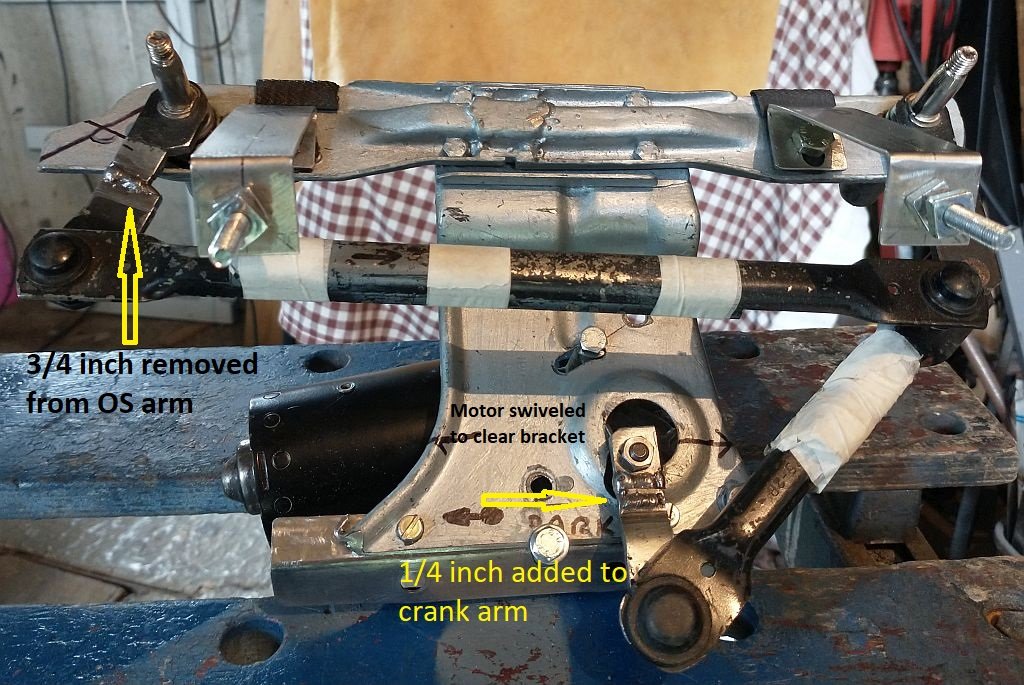
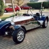
After a lot of trial and error ( I think it's called an heuristic approach) I have modified the Sierra wiper mechanism to give a better sweep of the blades, the drivers side now has just over 130 degrees and the passenger side (which was never a problem) has around 100 degrees. The photo below shows the hacked end product. Adding length to the crank arm only gives a marginal gain in sweep because it soon fouls the bracket and also means changing the length of the attached arm to a point where the mechanism becomes "unstable" and can easily lock up as the joint flexes in the wrong direction from the nearly straight position, a bit like your knee suddenly bending the wrong way when you try to kneel. Now I can move on and try to get a decent weather seal around the turning shafts that are coming through the scuttle.

-
As you say, the headlights via the ignition is up to you, On my car the headlights come directly through the ignition switch and the dipped lights come from the battery BUT via a relay that is poered through the ignition switch, this is how it was wired on the 1986 Sierra, although older cars don't have a dipped beam relay and younger cars have relays for both dipped and main beam. I think if you search the forums you will find this topic has come up before. Now the flashers. I have looked in detail about how they operate using the Sierra loom, and I assume you are using the Sierra stalks ? So here is a brief description that hopefully explains which contacts on the stalk and flasher uniit are used an included the Sierra loom wire colours. The flasher relay has 3 contacts, 31/brown-Earth,49/(black/red)-power, and 49a/(black/white/green)-output to the L/R indicator switch contact 49a on the steering column switch that has the l/r indictor switch and hazard warning button on it. In normal operation the column switch takes power from a fused contact that comes via the ignition switch to pin 54(Black) and it's output 49 feeds flasher contact 49 which gives a flashing output on 49a that goes back to the column switch 49a (you can see the correspondance of pin numbering here). The column switch then drives output pins R(Black/Green) or L(Black/White) depending on the position of the indicator stalk. When the hazard warning switch is engaged a whole load of contacts on the steering column switch change. Now the power feed to the flasher 49 still comes from 49 on the column swich however it is taken from a fused link directly to the battery and not via the ignition switch, this input is at pin H(30)(Red) on the column switch. The flasher unit is unaware of where the power is derived, so it still produces a flashing output on pin 49a which still feeds 49a back on the steering column. The change of switching caused by the hazard warning being engaged now feeds the flashing power from 49a to BOTH R and L outputs, so all the flashing lights flash. Hope this might help check that your connections make sense.
-
Just a thought. Initially you suspected that the starter was not disengaging. You might want to check that it is not re-engaging after the engine has started. Theoretically this is simply to disconnect the feed to the starter solenoid after the engine has started. In practise of course this difficult to do safely, one would probably need to add an extension to the wire that goes to the solenoid so that it can be disconnected easily without hands/spanners etc close to the running engine.
-
Perhaps you could find a plastic end cap ? Something like:- https://www.comtecdirect.co.uk/product/emtelle-pvc-duct-end-caps/PG4330 This one is just under 100mm, don't know the diameter of your cap. You could trim the length and perhaps wind tape around the outside of your cap to get a tight push on fit. Cut a round hole in the middle so that the key goes in. Then you could form a correct radius to get through the test, and it would not look like a temporary fix.
-
I knew someone would advise using the Mini/BMC type mechanism, it's just so obvious, the problem is with my attitude not to let the bone go, it's a case of "I've started so I'll finish syndrome" ISSIF. I have now extended the arm by 10mm and remounted the motor. The added sweep is not great but welcome. As Bob says I can see that if the slave arms are shortened then this gives a better "bang for the buck", also this has the advantage of choosing a different sweep for each wiper AND only one cut and weld on each arm AND the effect can be trialled by temporarily overlapping the cut arm to set the added sweep to exactly that needed. Thanks for the suggestion, I'll keep you posted.
- 8 replies
-
- 1
-

-
- modification
- sierra
- (and 1 more)
-
I dismantled the wiper mechanism from under the scuttle and set about making the mod. There is a major problem. The arm that is to be lengthened already comes very close to the "backplate" to which everything is bolted, i.e. the linkages and the motor/gearbox etc. G. Cash gave me a spare wiper assembly, but this is the same, the arm comes close to the backplate. Obviously, I am missing something here ( yes I know, use Mini wipers etc.) ... as I see it the only way to extend the arm is to move the drive shaft by re-mounting the motor and gearbox further away from the potential contact point. I can see that this is possible, but no one has mentioned this. Its all puzzling.
-
At last I have the windscreen fitted on the Exmo, and have just managed to mount the Sierra wiper mechanism which I have modified as per the build video. I have made shorted arms and blades, so far so good. I put it all together and set the motor going. No bangs or crashes, so the clearences are okay. However, it's obvious that the sweep is not good enough. On the driver's side it is just about 90 degrees, i.e just 45 degrees each side of vertical, this might just be ok to see through on a wet day, but then the park position leaves the wiper well up the screen. I have searched through the forums and unsurprisingly this topic has already come up before. I quote the ones that I found below. It seems that the perceived wisdom is to add 10mm to the short arm that is attached to the motor spindle. Before I do this i am wondering if anyone has anything further to add to the wisdom on this subject, apart from telling me to fit Mini/old BMC type wiper mechanism. https://www.rhocar.org/index.php?/forums/topic/4337-sierra-wiper-motor/&tab=comments#comment-31292 https://www.rhocar.org/index.php?/forums/topic/5338-sva-with-windscreen/&tab=comments#comment-40054
-
This is a very interesting question, the sort of thing that hits you by surprise when you return to the car after purchasing the ticket. I did a bit of googling as to what motorcyclists do, and saw the advice to do as emptyat has said. A govenment document on motorcycle parking has the following paragraph "There is potentially a problem with Pay and Display, in that tickets displayed on motorcycles can be stolen. Moreover, the adhesive backing may be on the wrong side of the ticket to permit display on the front of a surface, as opposed to inside a windscreen. One solution to these problems has been implemented by Birmingham City Council, who provide a secure box into which motorcyclists post their Pay and Display ticket, having written their registration number on it." This made me think of another way of displaying the ticket, how about having a visible flat surface secured to the car and using a glue to stick the ticket to the surface. A glue that would mean destroying the ticket to remove it. So one would purchase the ticket, write the reg on it, photgraph it, stick it on the surface. Further tickets could just be glued on top. The surface could be engineered as to be easily removable using some sort of security bolt and key, and stowed out of sight when not in use. OR ... have a hinged perspex cover that is secured on top of the flat surface to prevent the ticket getting wet. Oh yes, another thought... if you use something like a steering wheel lock device whenever the car is parked you could fix the flat surface to the locking device. I use one of those that have a long bar to prevent the wheel from turning, the flat surface would be easily visible if it was fixed to the bar, say with tight jubilee clips.
-
The VIN on my Exmo was allocated a long time ago, I had no choice then along the lines of what Brumster says above. I paid a local garage to stamp the VIN in the driver's side floor and on a piece of SS that I then cut into a tab to rivet near the battery. They made a slight cockup, one of the digits (a 3) was punched upside down. They did it on the floor first, so also repeated the mistake on the tab for consistency. This odd VIN has caused a few smiles but no complaint from the SVA tester or the MOT testers over the years. So if you add the possibility of upside down characters into the Nelmo stats you probably get more possibilities than atoms in the universe ? ... no wait a minute that can't be right as the univers is infinite ... or is it?
-
I have been Googling this, always a dangerous thing. However I have watched several tubes on performing alignment using the "string method". I think the best of them, is seen on the link below. The presenter is very methodical in explaining the process I think he says it is what his car racing team use on a regular basis for setting up the track cars. He focuses on the importance of forming a perfect rectangle symetrically around the car, however I think the important point is that you set up parallel straight lines on either side with the wheel centers of each axle equidistant from the line. He also explains the relationship between Toe In using degrees and distances. I will be trying this method first to see if it works, but I don't have a rolling chassis at the moment, so am interested if LewisH tries this first. https://www.youtube.com/watch?v=IxnK1XE6ZAA
-
This is great news, here I have been messing about with all the physics and mechanics of caster and camber etc and all the time the solution is getting toe in correct. This is the most easily adjusted of all the steering geometry variables. What i don't know is what is the correcy value ?? Two above posts say "far too much toe in" well the obvious next question is ... what was the correct amount of toe in ?. The Haynes manual for the Sierra Saloon/Hatchback/Estate says that the optimum should be just 1 mm, with a minimum of 0.5 mm and a maximum of 4.5 tolerable. Can you remember what value was used on your vehicles ?
-
As you have probably found in your search, I asked this question not that long ago, in the thread:- https://www.rhocar.org/index.php?/forums/topic/49176-exmo-caster-adjustment There is a rather american voiced, but well explained Youtube about self centering:- https://www.youtube.com/watch?v=wLbs8kBXgrw On the Exmo, we can't push the bottom of the struts forward too far because the springs will foul on the leading side of the "n" shaped mounting outrigger. If the "front suspension springs fouling against chassis turret." means that they are fouling the trailing edge, then you have some hope because pushing the strut bottom forward might cure both problems. On my Exmo there is no self centering, however it passed the old SVA test without any mention. I want to fix it because it makes steering feel more like using a rudder on a boat, requiring constant attention to keep going in a straight line. Self centering can also be affected by something called the "King Pin Inclination", however we cant adjust that becuse it is set in the casting of the stub axle at the strut bottom. A property called camber we can in theory adjust by increasing/decreasing the distance between the either the strut tops or bottoms. A certain amount of negative or positive (I am not sure which?) camber can help with self centering. I think its negative camber where the tops of the wheels are closer than the bottoms. This means that when the steering is turned from straight there is a slight lifting of the car involved. Thus when the steering wheel is let go the energy is released by the wheels returning to straight and the car dropping slightly. Problems with this is that the steering becomes "heavier" and the tyres will wear on one side......I am toying (just toying) with the idea of being able to adjust the camber by being able to slide the top mounts in a short groove rather than the current fixed hole....I'll need to take measurement to see how much that could change the camber by, and the safety aspects etc. etc.
-
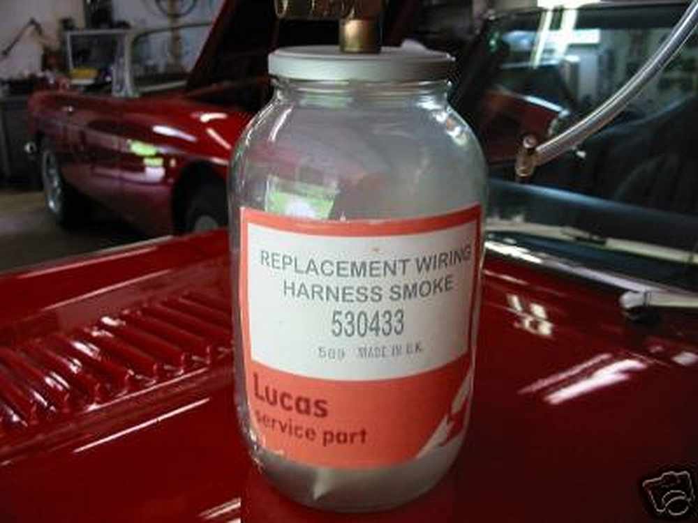
That wire, that you have no clue as to what it is for ? ... It is always the wire through which you inject the Loom/Harness smoke.
-
Well done with the rear wheel arches, it was a big bullet to bite. From where did you source the silencer ? how does it sound ? it looks like it can be repacked ? Also what a cliffhanger of a statement "....or so I thought" .... when is the next installment? ... on the edge of seat.
-
Engine turning slightly but starter new and new battery
Sparepart replied to Andrew Arcaro's topic in Mechanics
Watching and listening again to the vid, the clicking is obviously the starter relay cutting in and out and sometimes holding, at which point the motor turns but slowly. Two things happen when the solenoid is energised, the solenoid pulls an arm that pivots to push the starter dog and engage it with the flywheel cogs, at the same time it closes an electrical switch that connects the battery to the motor. The switch has to make a good enough contact to pass the high current needed by the motor. So a possible cause of the problem is low voltage/current in the circuit that powers the solenoid, sometimes it barely has enough energy to engage the cogs and close the contact but the sudden added slight drop in voltage due to the motor starting causes the solenoid to drop out, then the motor drain stops and the solenoid has just enough power to re-engage, and this process repeats causing the rapid clicking. When the solenoid manages to make prolonged contact, enough for the motor to turn, it still only holds the contacts of the internal switch together weakly and not strong enough to pass enough current. Obviously the power to the solenoid is either coming through your ignition switch, in the start position, or via a relay that is driven by the ignition switch, depending on your cars wiring. In any case you can test this theory by energizing the solenoid directly from the battery rather than using the ignition switch. You need to be careful, make sure that the car is not in gear etc and with care connect the thick lead (positive) coming from the battey to the solenoid terminal on the starter (disconnect the wire coming from the ignition system), be careful, connect a thickish wire to the solenoid first before touching it to the thick wire terminal from the battery positive or directly to the battery positive. If this way of powering the solenoid solves the slow turnover problem then it indicates that the problem is with the power coming from the ignition system, and not starter power or earthing etc. If turnover is still slow, and the clicking noise occurs etc .... well at least you have eliminated something that might be a problem. P.S. Warning, if you have not done anything like this before, be prepared for a bit of sparking when you touch the wire to the positive terminal and the sudden activity from the starter that it generates, which will continue for as long as you make the contact. If you left the ignition switch on, then the engine might start to add further drama and the need to stop the contact immediatly, just like when you hold the key in the start position and then let it spring back. -
Engine turning slightly but starter new and new battery
Sparepart replied to Andrew Arcaro's topic in Mechanics
Have you performed the tests described in the service manual ? section 9 of chapter 5 "Starter motor - testing in the vehicle". If you don't have a copy then you can try and download the pdf from the link below. https://musse67.mbnet.fi/Taunus/Korjausoppaat/ -
I think you need to accurately identify the WW mechanism. Many builders have used the old Austin/Morris/BMC type of mechanism, where the motor drives a spiral cable inside a sheath. Two small gear boxes are attached to the cable where the spiral motion is converted to a reciprocating motion to move the wiper arms. When this mechanism is in operation the only obvious moving parts are the wiper arm shafts coming out of the little gear boxes. This is good as it means other parts of the under scuttle clutter are not likely to get caught up in the mechanism. Even better, the little gear boxes are mounted through a hole in the scuttle that has an inbuilt water seal setup, AND the distance between them is adjustable, this is why they are so popular. You will immediatly know if this is what you have, because (I may be wrong) all other mechanisms involve a motor that drives a crank arm that in turn pushes and pulls two longish arms, each one driving the wiper arm shafts back and fore. These mechanisms have a fixed distance between the wiper arm shafts and in operation the various arms/levers are VERY visible and take up quite a lot of space, which must be kept clear of any other items under the scuttle. Also frequently they are designed to be fitted outside of the weather proof part of the car so there is a challenge to weatherproof the area where the shafts protrude through the scuttle. ..... I find myself rambling on a bit and have got off subject ... so will stop now...... you need to identify the exact wiper mechanism before you wire it up.
-
-
Spec gives a range, 100% at 44A, 60% at 57A, 15% at 115A and 8% at 130A. You can draw a curve to predict intermediate values. So at 44A you can weld away forever and at 130A you will drink a lot of tea ... or might go down the pub. Personally I have not yet had it cut out yet, but do tend to weld in short to medium bursts mainly because I find it hard to wear my specs with the mask, so don't, and then have trouble seeing where the weld is going, so keep stopping to check. I get so close to the action to see properly that the glass is pitted with blobs of sputter, ah ... sputter another good topic
-
A small amount of Googling appears to suggest that Brooke is up for sale, if you have £500K to spare you could buy the company https://www.rightbiz.co.uk/buy_business/for_sale/226025_devon.html
-
For me the Clarke 135TE kit has been all I have needed for the work on the Exmo. It came with enough accessories to start welding mild steel, within half an hour of getting it home I was welding away. The mask in the kit is useable but a light activated mask (£40 ish) is a MUST to avoid accidentally burning your retinas, keep the one in the kit for the next solar eclipse. Since then I have used Argon and Argon/CO2 mixtures to weld SS (using SS wire of course) though the welds look good in SS there is a lot of opportunity for error, in as much as thin SS is very easily warped and there are different compositions of SS that can mean the welded metal changes its molecular structure and makes it prone to rust. Something you might notice on SS shells. This is what I mean about a Pandora's box, the chemistry and physics and metalergy involved in welding goes on and on. I have purchased some aluminium wire to try, but am still at the stage of watching You-Tubes of how to use it ... another world of alloy types, temperatures etc. I still use the Arc welder, but only for more "agricultural" welding of thick iron/steel like repairing the hinges on a friend's shipping container or fabricating angle iron fence braces and the like... especially if the welding is outside ...where the wind would blow away the shielding gas of the MIG welder.
-
Ah, I see... possibly thats where most flexing must have occurred, I guess a chain is as strong etc. if one place is strengthened it tends to put strain on the next weakest point and one hopes that the weakest point is strong enough. I'll adopt the "regular checking" approach, like the ritual that pilots take a walk around their aircraft before every flight. Thanks for the insight.
-
I fear that you are opening a Pandora's box with that question. I have learned to weld after a fashion by trial and many many many errors. In retrospect what I should have done was to take the time and expense to have proper instruction. As you know there are three main types, Arc, Mig and TIG. I "started out" with an Arc welder because there is less complication, just the welder and welding sticks and mask and gauntlets and apron to buy. However I soon found that arc welding is more of an art than a science, one needs to understand so much about how air is kept from the molten metal during the welding process, not only the physical movement of the welding stick but also the chemical composition of the flux and its relationship to the type and thickness of the metals that are being welded AND taking into account the temperature of the weld. It is VERY hard to weld thin metal with an Arc welder. Also I never got to try and purchase Stainless Steel welding sticks which I assume are expensive. Basically I GAVE UP with the Arc welder. Then I purchased a Mig welder, Clarke 135TE from Machine Mart. Although it is more complicated, wire spools, gas cannisters etc I have found it so much easier than Arc welding, once the correct wire speed, current and gas flow has been set up. TIG welding is yet a mistery to me, involves coordinated movements of two hands, one holds the tungsten tipped arc generator that gives high temp and the other feeds a metal rod into the molten pool that forms the weld. So I would say your are best to start with a MIG welder and I advise you to get some instruction, or get a load of scrap metal on which to practise. Oh yes, also, some of the welders out there require more that a 13 amp power connection, beware.
-
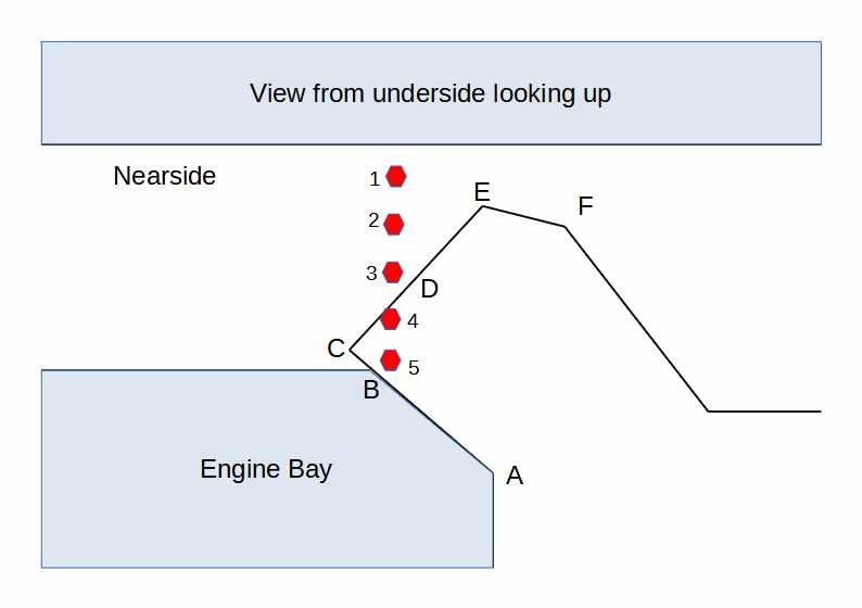
Thanks for the replies, reading around it seems that people have found cracks in various places around the area where bolts clamp the panels at the end of the footwell together. I insert a drawing below, I assume that the crack mentioned by IanS would have been between bolt 1 and the side of the body. I wonder was it visible from above or below or both. Bolts 1,2,3 and 5 go through 3 sheets, and bolt 4 goes through 4 sheets. I am wondering if its worth doing any pre-emptive strengthening here, maybe more plate or converting the bolt holes into big spot welds ?. The other approach is to leave everything as it is and check for cracks regularily, which is what I think most people do because it's hard to predict the failure point (if any) in this area. Comments?.
-
Obviously I do not have a CBS module to test with, however I think that you should find that terms 5 and 6 are connected together inside the module. You can easily check this out, you might even be able to see from the underside if they are the same plate of metal, otherwise use a meter etc. One thing that I have not mentioned before is the circuit protection for everything (bar the starter and alternator) that is powered from the battery. You could think of it as the "main fuse". If you look at the diagram you can see that all the power that is taken from the battery (except that in the thick wire to the starter) will be drawn through the wire connected between the starter and terminal 6. In older cars (pre 1999 say in europe, and most US cars) the wire connecting the battery to all the other electrics (except the starter) is what is call a "Fusible Link". That is to say, the type of metal in the wire, and it's thickness is designed to melt if the current goes over a certain amperage, typically say 60 amps. So the fusible link is a hidden fuse that protects against major short circuits. Modern european cars actually have a descreet fuse for this frequently to be found close to the battery terminal. Anyway, I hope that you can see that it is preferable to connect the alternator to term 5 and the battery (via the starter) to terminal 6, in this way you can, if you want install a "main" fuse either by using the fusible link from the old donor, or a more modern fuse. Although there is nothing wrong in connecting the battery to term 6 via the starter motor (because of the thick wire from the battery to the starter) it is also perfectly acceptable (and more usual) to connect term 6 directly to the battery positive terminal, either way through a "main" fuse. I hope all this talk of fuses is not con-fusing :-).