Sparepart
 RHOCaR Member
-
Posts
351 -
Joined
-
Last visited
-
Days Won
14
Content Type
Profiles
Forums
Events
Store
Community Map
Everything posted by Sparepart
-
No I have never done this. However if you look at this adapter as part of the ATR remote reservoir kit you will see that it uses a fibre washer as a liquid seal. I attach an image that I scraped from their catalogue. In your picture above I can see you have a washer but it's not clear if its fibre. Oh! just thought it might be copper not fibre.

-
It all depends on whether you want an expansion tank or an overflow tank .... they are different. See the Youtube below for a description of both set-ups. Also see the link to a description of how the cap lets out excess pressure/fluid when engine hot and can suck back air/fluid when cooling. https://www.youtube.com/watch?v=jkhYt-OaipE http://www.mgb-stuff.org.uk/radcap.htm Hope these help you decide.
-
In the blurb "Individual Cars. We have been in the motor trade industry for over 40 years" yet they say its a 2B and its a series 3, no underbonnet snaps, and in the snap of the spares the donor engine block has been placed with the exposed cylinder head mating surface down on rough paving. All not very reassuring.
-
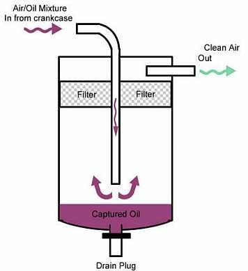
Your photo appears to show a standard Ford vented oil filler cap, the one that has vents on the underside of the mushroom and a hole in the middle in which a wire gauze can be seen and an O ring seal on the outside (I think). This is adequate, wash it out with paraffin and let it drain to make sure it's not clogged up. As you are going for the catch can option the inlet manifold will not be sucking any fumes, so no vacuum possible in crankcase, so theoretically no vent in oil filler would be needed, however it can't harm. Although if your engine gets badly worn or a piston ring leaks badly then you could get fumes and oil mist coming out of the vent in the filler cap. I'd like to think that you would fix the engine before it got that bad. It sounds like you have a good enough catch can. It doesnt need a vent because it IS the vent. That is it is the way that excess pressure is going to escape the crank case. There will be an in pipe and and out pipe. In from the crankcase out to the atmosphere. These should be marked on the catchcan, if not open it up, the IN pipe should go down into the can below a baffle or filter and the OUT should come from the top of the catchcan. As well as routing the in pipe so as to avoid a syphon of oil when cornering (read Dave Andrews) try to position the end of the out pipe where a flow of air under the car will serve to draw fumes out. Do not point the end of the pipe into the airflow under the car because this will blow air against the venting fumes and ruin everything. Something like at a 45 degree angle towards the rear seems practical, if you could also bend the very end to be in line with the airflow like the left half of a "U" then so much the better.
-
Hi, are you sitting comfortably then I will begin. Don't panic. Go back to basics and work from there. What is going on here ?. If the pistons and rings formed a perfect seal in the cylinders then everything that comes in through the inlet valves would exit via the exhast valves and in the crankcase below the pistons there would be a lot of oil splashing about but no increase in pressure, the air volume wont change because as two pistons travel down, two are travelling up. However, this is not a perfect world, even from new there is a leak of gasses past the pistons on compression and combustion, as the engine wears this leak increases. If the crankcase were sealed there would be a build up of pressure which eventually would blow fumes and oil spray out of all the weakest bits of the crank case, like the filler cap, dipstick, crankshaft and camshaft oil seals etc. Clearly this would not be good. For most of the history of internal combustion engines this problem has simply been solved by providing a vent somewhere on the crankcase, usually in a place where there is a minimum of oil splashing about. The vent pipe would then go into some form of oil trap to "catch" condensing oil droplets before being routed under the vehicle to a position where air flow provides a slight venturi effect to help draw out gasses. Note that with this simple setup there is not really a need for any other vents. In recent times, 1980s-90s the escape of the fumes into the atmosphere is frowned upon, and I think in some markets illegal. Today all vehicles are fitted with Positive Crankcase Ventillation (PCV). This is not complicated, what happens is that instead of the vent pipe simple being routed under the vehicle out to the environment and causing pollution it is routed into the inlet manifold where the vacuum sucks pollution back into the fuel and air mixture for comustion and exit via the exhast which now has the catalytic converter and oxidisers etc. to reduce emissions. However as with many things, it is not quite as simple as that, there are two things that come along with this solution. Firstly to avoid a build up of vacuum in the crankcase there needs to be an inlet vent, which is usually provided by a vented oil filler cap. Secondly the flow of gasses into the inlet manifold needs to be controlled to keep a steady flow regardless of engine load, otherwise the variation of vacuum in the inlet manifold will mess up the carefully metered air/fuel mixture. To do this a "PCV valve" is fitted to the vent pipe somewhere after the oil trap and before entering the inlet manifold. A clever little mechanically simple device that keeps a constant flow as the gas pressure/vacuum varies. So thats it really. If you dont care about pollution then use the old fasioned solution, which is what I think Dave andrews solution, however make sure that if your inlet manifold has a connection for the vent pipe then block it otherwise air will be sucked in. If you want to save the environment, then fit the standard vented oil filler, standard small Sierra oil trap, standard sierra PCV valve and connect the vent to your standard ford inlet manifold where there should be a place to plug it in. In your photos there appears to be a blue pipe that in two of them is connected to a filter and not connected in one photo, I assume this is the pipe that is spitting oil. I think you will find that this pipe is plugged into the block and is the vent pipe and that a previous owner has simple routed to in front of the fan so as to blow fumes and oil spray away under the bonnet. If there is a lot of oil then there probably is no oil trap or PCV valve further down. So simplest for you is to check that any connection point on the inlet manifold is blocked, which it most likely is. Then route that blue pipe to a simple catch can, there are many advertised online. Check that there is no PCV valve because without a vacuum from the manifold it won't work, although if you have fumes spitting out of the blue pipe then likely there is no PCV valve. Note Dave Andrews' warning about avoiding oil syphoning under cornering when you route the pipe to the catch can. The catch can will need to be drained occasionally, so some have a drain tap at the bottom. Phew, still reading ? thats enough!!
-
One thing to check would be the PCV valve. If it is sticking in the open position it will cause problems at idle and low revs. Just google "how does a pcv valve work" and you will find loads of info on it, how to check, fix etc.
-
Run without air filter so that you can look down the carb barrels. As soon as the engine cuts out look down the main barrel and open the throttle quickly to operate the throttle pump, if there is no squirt of petrol it would confirm an empty float chamber. If it always starts with Easy Start then again as IanS says it's going to be fuel shortage.
-
I am finding your description a just little confusing. By "compression struts" do you mean tie bars that can be adjusted, as opposed to the ARB that can't be adjusted.
-
Thats very clever, an elegant solution. One more factor to add into the considerations, the volatility of the fuel. Presumably the carb was designed before the days of E10 or E5 fuels, when there were usually two octane levels available, regular and super. The timing for a fuel that burns slowly woluld (I think) need to be more advanced than for a fast burning fuel. I guess that its important to keep using the same quality of fuel as you do all this experimenting.
-
Good news if it's a matter of getting the timing spot on. I just happened to read a small article in PC magazine in the problems section someone was trying to cure spark plugs getting carboned up (I'm assuming poor combustion and emissions would come with this) .. anyway among the items that the expert suggested to look at was the timing as one might have guessed, however he went further and also suggested checking the timing advance through the rev range not just idling. For example you might have vacuum advance on the distributor and a leak in the vacuum pipe from the inlet manifold etc. Also another suggestion was that the fuel pump might be providing fuel at too high a pressure for the carb. When idling the float is high and able to push the inlet valve enough to stop flooding, as the revs rise the float drops but the high pressure rush as the valve opens is enough to cause some flooding, then at higher revs the engine is taking enough petrol to prevent flooding. You might not need all this but I thought I'd mention it in case someone else looks at this thread later.
-
IF your Westfield is wired as per the referenced diagram then what happens right now at the relay is as follows:- Power arrives at pin 30 from the 3 posn switch when it is headlights on posn. It comes up the wire colored yellow in the diagram (which also energises the fog light switch). If there is no power on pin 86 (looks like 36 on diag) then the relay is switched to energize pin 87 (blue) which powers the low beam filament. The high/low beam switch is used to energise pin 86 which causes the relay to switch power to pin 87A, from 87, i.e. the low beam filament has no power and the high beam filament is given power, and also the high/low beam indicator lamp is illuminated. In order to implement a high beam "flash" function then another relay is not strictly necessary. A momentary switch could be added that enegises pin 87 directly from the live thats live when the ignition is on, so the lights could flash at any time the car has the ignition on, the best place would be from fuse that powers the first connection no 6 in the row of black terminals in the diagram that is for the lights. There is a potential problem with this however, and that is if the headlights are on and using low beam. In this case the "flash" switch would illuminate high beam at the same time, both filaments might draw too much current through fuse 6 and it might blow. So to rule this out, the "flash" switch could be used with another relay that stops power being given to 87A via the flash switch when 87 is energised (i.e. when low beam is on). Hope this makes a bit of sense.
-
I've done a bit of web browsing, I have no Westfield experience, so take what you will from the following. Have a look at the wiring diagram at http://westfield-world.com/wiring_diagram.html This is most likely what you have. You can see that the headlight relay is only energised from a switch that has 3 positions, off, side and headlights (probably blue rocker?) When the relay is energised it can have it's output controlled between High/Low beam by a second two position switch (what you call toggle I assume). There is no provision in the circuit to energise the Main beam independently, as you desire. To do this, as steveg suggests, you would need another switch and relay. This switch would need to be spring back to off when flicked on.
-
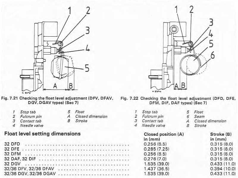
The maths of your percentages seems impecable. I'd have thought though that the level in the chamber is the important thing not the volume. You say that you have adjusted the float to what it is supposed to be, I wonder what technical manual you obtained the adjustment details from. Below I am including a table from the manual I have which shows two adjustments, level and stroke, perhaps you could check your carb against this. Also could a small leak in the float reduce it's boyancy.
-
I don't have this carb, I have DFTH 30/34, however in order to recondition it I got hold of a Haynes manual for weber carbs, and chapter 7 covers DGV 32/36. Looking at it there is a description of what happens from cold start all the way through to hot on full throttle. In the bit about normal running it mentions air being drawn through the "air corrector jets", perhaps this is a factor. In the section on fixing problems, there is a mention under execessive fuel consumption of an incorrect level in the float chamber. Hope this might help.
-
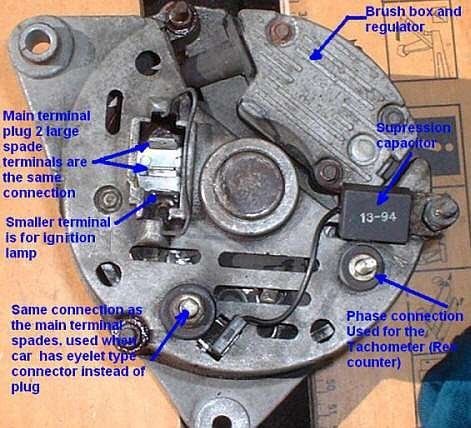
I have done some investigation of the photos of the alternator that you have. I found an article about rebuilding an alternator that looks very much like yours, here is a photo from the article. It looks like you have overkill on the charging cables, in that the big thick cable and the two large spade terminals are all delivering the output from the alternator. I'm gessing that at the starter motor there are two thick cables bolted to the same terminal, one is this one from the alternator and the other then runs to the battery. As the label on the photo here says, the smaller terminal is for the ignition warning light. The warning lamp lead serves two purposes. When the engine is not running, the alternator is not generating a voltage, the warning lamp is also connected to the battery, so a small current will flow from the battery through the lamp (illuminating it) and to the alternator and then the alternator earth. This small current is used by the alternator to start energizing the field coils, so that the alternator can start to generate voltage (and current). Without this small initial current through the alternator it will turn but not produce output. As soon as the output from the alternator reaches a voltage equal to the battery (12v) then the small current through the warning lamp ceases, and the lamp goes out. That's why the "ignition light" works the other way round from normal warning lamps, i.e. it goes off when all is ok. It is not necessary use a lamp to provide the small current, a resistor with the same value as the warning light resistance will do, it's just convenient to kill two birds with one stone. When some people replace all their waring lights with LEDs then if this warning light is replaced, the current flowing through the LED is too small to energise the field coils, and a small cuircuit to wire a resistance in parallel will be needed..........i'll stop now before I bore my own pants off.
-
I agree, the Haynes manuals for the Sierra helps for Pinto, and also for all the other bits that come from a Sierra donor used in RHE and other kit cars. The most detailed one is the "Owners Workshop Manual" ISBN 1 85010 538 3 (1982 to June 1989) .... but hard to find. The other one is the "Service and Repair Manual" ISBN 1 85960 090 5 (1982 to 1993 K reg) easier to find. Here is a link to a copy for a fiver. https://www.gumtree.com/p/books/haynes-manual-ford-sierra-82-93/1479713537
-
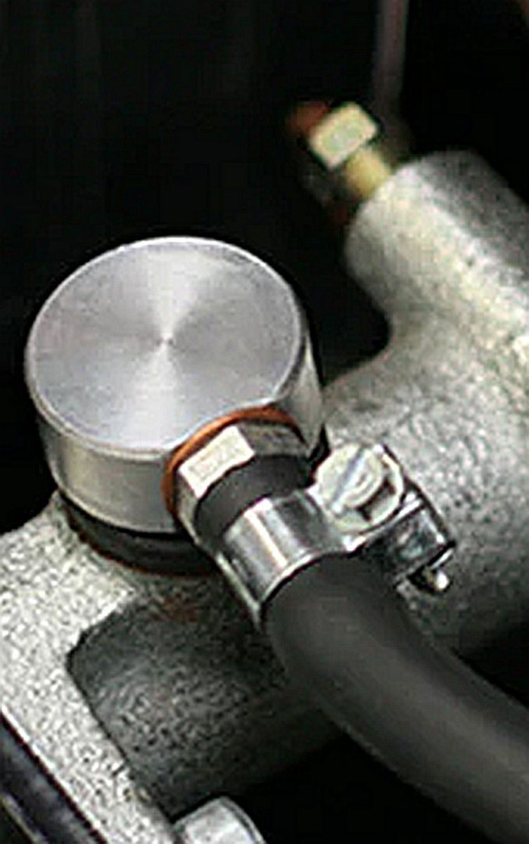
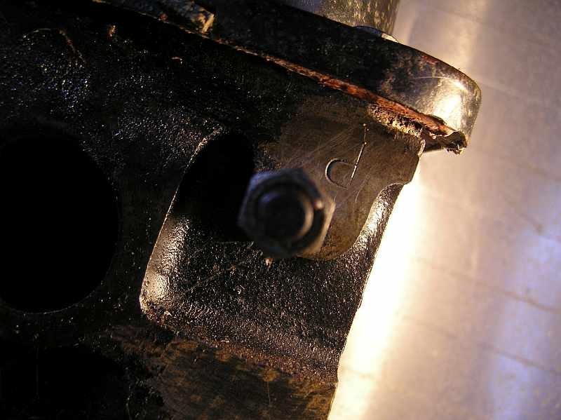
The sensor in the picture is screwed into the threaded hole that is usually used to drain the coolant from the engine. So it normally has a simple blind threaded bolt head showing. Looking at the PTFE tape that appears to be in two places on the "sensor" I'd guess that an adapter has been used to reduce the hole diameter to the size needed to fix a water temperature sensor, probably for a gauge. Before you ask, the other blind bolt head that is in the photo lower down on the crank case is sealing the hole that is used on some (high spec) models to mount a sensor for a low oil level warning light. I dont know of any drawing for all the sensors. The sensor for coolant temperature is on the other side of the block, just above the disributor, and the oil pressure sensor is also on this side lower down not far from the starter motor. If you have a standard carb inlet manifold (I don't think you have) then depending on the ignition control module there is another coolant temperature sensor on the manifold.
-
That mark that looks like an F is enigmatic, not quite a proper stamp, but unusual if its just by chance. The head on my Pinto is stamped with the letter P, but it took me a while to find it. Why? ...well its stamped next to Number 4 inlet port and can only be seen properly when the manifold flange is removed AND it upside down with the engine in place. My assumption is that it was stamped when the head was not on the block during manufacture.
-
I suggest that you scrape the paint off the machined flat surfaces next to the no 4 spark plug, it will then be clear if there are any markings there. If you find an * stamped then look on the other side of the head near the inlet port for no 4, (look there anyway). I have picked up the following information from the various threads on this frequent topic. It might be of use. N.B any marks will be punched not "scratched" or cast in the mold. Unleaded I/D for Pinto next to number 4 spark 1.6-- M,MM,N or NN 1.8-- S or SS 2.0-- P,PP,R or RR Have a look at the shape of the inlet ports. If they are round its no help but if they are cam lobe shape then its an injection head and is unleaded. 'I' OR 'L' stamped next to number 4 spark plug hole= a leaded head most likely to be 1979 - 1982 in age
-
One assumes thatyou have looked at the literature links in the Wikipedia, like the Steve Hole A to Z book, perhaps not because of the cost. Some car shows on TV seem to be able to let the viewers know how many of car type are still on the road, also classic car magazines ... so how do they find out? The .gov.uk site has a page where you can start making an enquiry https://contact.dvla.gov.uk/vehicle/capture_transaction_type?locale=en&transaction_type_id=requesting_information_from_dvla_vehicle_records
-
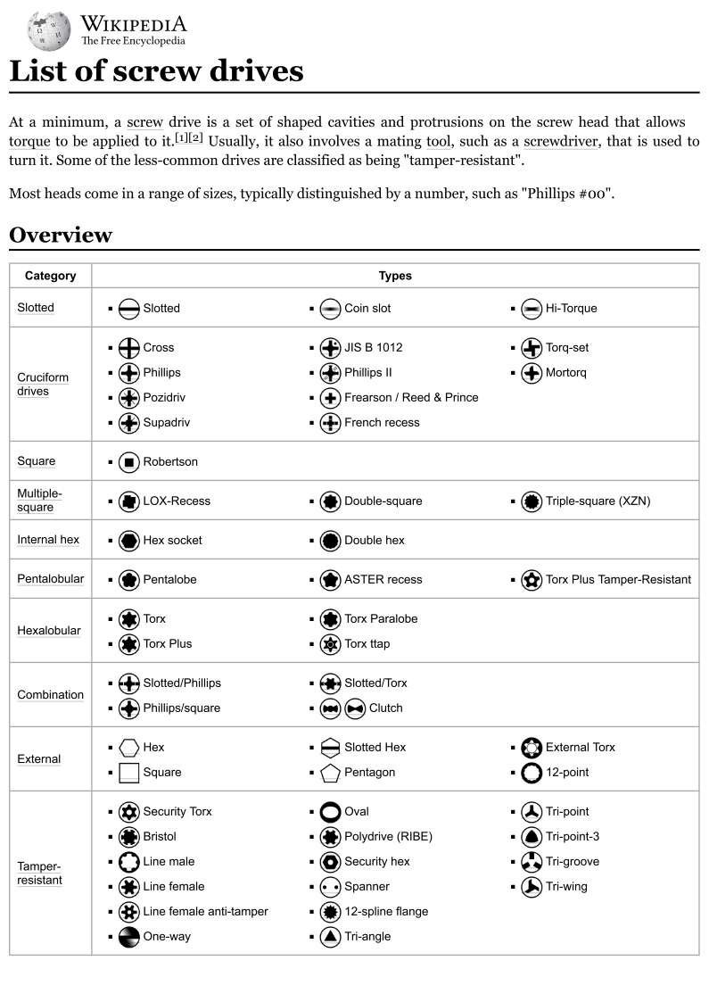
I have done some more digging around, and believe I can now answer my own question, which has been raised in other Ford related forums. The type of spline bit needed is XZN "Tripple Square", the profile being three squares overlayed to form 12 corners of 90 degrees equaly spaced around the circle. At least this is what I am going to buy, I will be after an 8 mm bit of this type. A hex key might work but it wouldn't have 90 degree faces, a square drive would probably be a better fit. I'll update this when I get hold of the XZN to try. In case of interest I am attaching a page from Wikipedia that shows the range screw head types in the world, might be useful if you are trying to find what the head that you see is called.
-
I have changed a pinto cam belt, but not for a while. I know I have the splined bit that fits the tensioner spring bolt somewhere, BUT where did I put it! ... So many spiders are now homeless in my attempts to locate that strip of 4 or 5 splined sockets/bits....... so I need to buy some more ..... but now I look on-line and am amazed by the number of different splined sockets/bits available, I don't mean different makers, I mean different standards. The one the block that I have looks like it has 12 points, then I see 3 different standards of 12 point splines (at least) depending on the angle between the teeth. I did find a set of bits handed down from my father, but when I tried the one that looked the right diameter it started to go in but was obviouly the wrong tooth angle because it started to make grooves on the sides of the bolt teeth. I searched our extensive database and found the link below, however apart from telling me that a hex key might be ok, there is no definitive information abount exactly the type of splined bit needed. Does anyone here know the details ? https://www.rhocar.org/index.php?/forums/topic/25924-cam-tensioner/
-
I did this last autumn without this problem, following the manual as you have. Perhaps the seal has not gone into the housing all the way, and might be wedged out so that it is fouling the inside surface of the flange ?, or might have been proud and has now been pressed in by the flange and just needs to be tapped in a bit further.
-
Yes, you are correct, I attach a snap from the manual.