Sparepart
 RHOCaR Member
-
Posts
351 -
Joined
-
Last visited
-
Days Won
14
Content Type
Profiles
Forums
Events
Store
Community Map
Everything posted by Sparepart
-
Nelmo is correct, this is one of the most "skill testing" parts of the build, I am fairly shure that the 3A is the same as the Exmo with regard to this. I have completed this after a fashion. The original kit contains only the "raw" components, you would need to have these even if someone else does the work. From memory the bits are:- Two pieces of pre-bent aluminium channel to make a frame, a toughened glass windscreen, two thick flat steel support brackets (roughly cut by plasma), a roll of flat thickish rubber strip to go round the glass when it's in the frame, and two stainless steel self tapping screws to clamp the frame together once its been cut to size. The kit did not contain a wiper motor mechanism, it was to be taken from the Sierra donor and modified to reduce the distance between the spindles. The spindle holes were pre cut (rough plasma again) in the scuttle, BUT the screen support mounting holes in both the supports and the scuttle sides were not pre-drilled or pre marked. The jobs to be done, simply stated, are- Cut and fit the frame to the glass with rubber inserted using various clamps, loads of parcel tape, rubber mallet, drilling holes across mitre joints and securing with self tapping screws, all without breaking the glass. Position the framed screen on the scuttle to find the sweet spot for the bottom curve match to the scuttle, mark position. Make two bends in the flat supports, one is to match the radius of the scuttle at the sweet spot, the other a twist in the upright part to square up the screen edge. Drill holes in supports and scuttle. Now with great care drill holes in the side of the frame without breaking into the glass to fix the screen edge to the support upright. Tighten everything up and voila! ...........I hope this gives you a flavour of the work involved. Most people do not fit the modded Sierra wipers, or if they do they ditch them shortly after... then fit BMC type wipers as per Mk1 minis, morris, austins etc.... If you or someone wants to go ahead with this I could send you DVD copies of the Exmo build instructions that have got all the standard procedures in gory detail. Oh, yes of course the hood cant be fitted until the windscreen is there and this post has gone on far longer than I intended, a bit like fitting a screen.
-
If you are looking for the connecters that push on to the threaded posts on the coil ? ... why not buy a pair of spade terminals to bolt on the coil then you can use the easy to get spade connectors. For example https://simonbbc.com/coil-spade-terminal/
-
Why not try Prestone.... it's the answer to everything. I attach the product info.

-
How about using a pressed steel type joint, it might tighten up better on your splines. https://www.burtonpower.com/steering-coupling-gp4-ford-escort-mk1-mk2-pressed-steel-type-mp207.html Alternatively, you could try drilling out the hole on the clamp by say 2mm to take a wider bolt and then carefully filing a groove in the splined shaft end so that the bolt only just slips through, this could both prevent the shaft pulling out and stop it slipping round.
-
If you are using the usual 21 watt filament stop lights, the reed switch needs to comfortably handle 42 watts (2 bulbs) at 12 volts, i.e 3.5 amps. So you need a swich that is rated above 3.5 amps at a minimum, the more above this the better.
-
Did you do a search for this topic ? you might already have found this https://www.rhocar.org/index.php?/forums/topic/49808-fuel-sender/ . Notice that the Sierra sender has a pin that increases resistance as the tank empties and one that goes the other way decreasing resistance as the tank empties .... might explain your comment about your gauge reading backwards.
-
If you have repaced the ignition warning bulb with an LED bulb, then that might also prevent the alternator charging, can be seen because the LED appears to be constantly turned on when the engine is revving.
-
Luckily my standard size 10 feet seem to work well with the position of the Sierra pedal box on the Exmo, so the clutch and brake pedal positions are ok, however the throttle pedal was not in a good place to indulge in a bit of "heel and toe". This was easy to remedy because the throttle pedal is idependent of the pedal box and is easily moved up or down as long as you are willing to make a new hole for the cable to run out from the top of the pedal. Lowering the pedal box to lower the pedals would not be easy on the Exmo, and would bring the brake servo/ master cylinder even closer to the hot exhaust pipe. The Bob Tucker solution sounds simple and effective, an example of "vertical thinking".....
-
Possibly not just at the back of the fuse box, maybe somewhere along the length of wire from fuse to the gearbox switch might have been severed by someting when the ignition was off ?
-
I've not had to paint any of the blue bits on my kit, purchased in 1996, however I remember on the build video Tricky Dicky says that it is "Oxford Blue" Pantone 282. BTW you say your RH is 1989, yet the member bit on the left has you as having a 2B .... perhaps the donor was 1989 ?.
-
I agree, you don't want to be hacking away bits of bodywork. When you remove the seats, on each side you should find a large roughly rectangular thick steel plate It is bolted to the SS floor. The large bolt in your picture comes up through the middle of the plate so you can undo it. The outside edge of the plate is bent up at right angles and a bolt goes through it and the bush that you want to replace. In your photo of the "bad" bush you can see the edge of this plate to the left of the bush. The big round bush with the big bolt is set in all that rubber so no matter how tight that big bolt is, it still can move about. Whereas the right angled flange connects more firmly to the subframe. So the big bolt and the bolt through the flange will hve to be removed along with all the other stuff the IanS mentions in order to drop the subframe enough to replace the bushes. In the case of an Exmo, the SVA inspector insisted that a second vertical bolt be placed, not set in rubber, to fix the subframe firmly to the plate in the floor. So you might find another vertical bolt when you remove the seat. The head will not be visible in your picture because its up inside that hole just to the left of the big rubber mounting.
-
Interesting, I did not try this on my Exmo what I was afraid of is that the sump is below a quickly narrowing part of underbody that supports the engine mounting trays, they make a forward pointing V shape, it looks like the engine will not just slide forward as the sump gets wedged in the V, so it has to be raised at the front, so that would mean supporting the front of the gearbox in order to pull them apart, which raises the possibility of putting up or down pressure on the gearbox input shaft just before it pulls out of the spigot bearing or scratching the end on the clutch release mechanism. So, probably over cautious, I took the unit out joined and seperated the engine from the gearbox with them both level and a small trolley under each. Taking them out seperately avoides losing gearbox oil and probably makes fiddling with the speedo cable easier as the gear box can be moved closer to the hole in the transmission tunnel. Also of course if it's just the engine your after then why remove the gearbox. One other thing is the clutch cable removal. The clutch cable is normaly under some tension from the auto adjusting mechanism in the pedal box, this can be released to make cable disconnect easier by lifting the clutch pedal up as far as it will go and keeping it there with a piece of wood. This lifts a small serated cam off the adjusting quadrant that is hidden in the pedal box.
-
Took one out of an Exmo about 2 years ago ... lets try and remember ... Engine and gearbox are taken out together, it's a snug fit so everything you can do to make space is helpful. The unit must come forward but also up at angle, quite a steep angle in order to clear the top of the front cross member, so obviously radiator and viscous fan come off, I removed the nosecone just in case it would get biffed when sump came over the cross member. The RHE four branch manifold must be removed, and I did take off the inlet manifold with carb attached, probably not required but again avoiding inadvertant damage. Once the engine weight is on the hoist take the engine mounts off at the block and remove from engine bay. I also removed the starter motor and alternator, to reduce weight and increase manouverability. Obviously the gear lever, but also the speedo cable, which was quite tricky because it came out of a hole in the transmission tunnel which gave a very small apeture through which to get a circlip remover to release the cable from the gearbox. Also beware! since the propshaft cant be removed from the rear (not without taking the diff out) it stays in place and drops off the gear box as the box moves foreward, this makes a bang as the propshaft hits the transmission tunnel floor. ALSO .. at this point ... if you can .. try and get some cling film or plastic around the hole that the propshaft has just left. There is no drain plug on the gearbox. So as you fiddle around gradualy pulling the engine forward and up at angle the gearbox is busy draining itself out of the propshaft hole all over your nice clean garage floor. I guess a large pan like the one you do your Sunday roast in strategicaly placed during the removal might be okay to catch the oil, but makes the beef taste a bit odd later. Can't think of anything else at the moment, but there are probably other things I have forgotten. Good luck!.
-
If this is original kit, there was a large diameter thick washer, same diameter as the spring that sits directly on top of the spring, the hole at the centre of this washer is large enough to sit just on the outer ring of the bearing. The bearing then goes on top of the large washer. A small but thick washer then goes on top of the bearing wich sits only on the centre ring of the bearing. The body buttress then sits on this washer and the bolt is tightened down. So the shock absorber inner rod is fixed to the buttress and the inner part of the bearing. The top of the spring, where the body weight bears, pushes up on the outer edge of the large washer and therefore the outer ring of the bearing, and therefore via the bearing balls (if it's a ball bearing) to the centre ring and then up via the small washer to the buttress. As standard, with SS Exmos, the pressure of the body weight on this small washer caused the SS to crack around the butress hole, so most people put a thick plate on the underside of the butress to spread the pressure.
-
As I remember it, the new cable will have all the various components, two sheaths, plastic adjusters, some washers, and protectors etc. These are all threaded on to a single cable and then the nipples attached. The nipples will not run back through the sheaths, they are too big. So what you get is a symetric component, Nipple sheaths etc for nearside, a length of bare cable threaded through a new horseshoe in the middle and then sheaths etc. and nipple for the off side. Fitting on a Sierra is simple, just attach the horseshoe to the handbrake lever rod, thread each side through the subframe holes attach at each drum etc and adjust. The important thing is that the cable can slide back and fore through the horseshoe, this means that the tension on both sides is equalised, thats why Ford call it an "equaliser". When the cable is shortened by cutting off a nipple and pulling the extra cable through, cutting to length and attaching a new nipple, the "equalising" action is preserved because the cable can still slide at the horseshoe. I guess the cut could be made in the exposed part of the cable near the horseshoe and re-joined with a cable clamp, however the clamp needs to positioned so as not to either prevent the cable from slipping into the sheath when the handbrake is released or fouling the horseshoe when the cable moves to equalise the tension to each drum. Adding to this will be the confined space just above the propshaft UJ and the metal edge around the transmission tunnel which will make positioning of the cable clamp a bit of a challenge. (I don't know how hard because I didn't do it this way). Fixing a new nipple on the shortened cable end can be done away from the car at a workbench. So much less fiddling IMHO. Oh, P.S. I did this on an EXMO, maybe the S7 has a different construction of the rear panels ?. On the EXMO the propshaft emerges from the tunnel through a large circular apeture that has room for the horseshoe to sit just above the UJ with a few inches of the cable visible to left and right before they enter the sheaths that thread through the subframe. When everything is installed/adjusted etc. there is enough tension in the cable to stop the horseshoe from dropping on to the propshaft.
-
It's been a while since I looked under the rear of the Exmo, from memory, the "horseshoe" or "Handbrake Equaliser" as Ford call it is just above the rear propshaft coupling to the diff pinion. It is accessible without cutting any holes in the chassis. Are you sure you need to replace the cable ?. You say that the nipple came off. When the cable that runs through the horseshoe is shortened one of the manufacturer's nipples has to be cut off and a new nipple somehow placed at one end of the shorter cable. It might be that it is this possibly "homemade" nipple has come off, and all you need to do is re-make a better one ?. Either way you will have to place/replace the nipple. I followed the build video instructions on this, using an M10 or maybe M8 bolt (size matters because the nipple has to slip into a certain place) .. anyway I drilled a hole longways through the centre of the bolt, and cut off the head, so I had a section about 15 mm long. The centre hole was only just wide enough for the cable end to get through, as tight as possible. Then, with the cable end through the hole I placed the "nipple" on an anvil, and using a cold chisel and big hammer "crimped" it by pinching both ends from one direction and the centre from the other side. So far this nipple has not moved or popped off.
-
That looks great, couple of things I'd like to know, 1) what type of bearing have you used ? (Ball race or thrust ?) 2) Obviously the spring seat is ajustable, is the bump/rebound ajustable ?.
-
We have visited this topic before (search "fuel sender") here is the link https://www.rhocar.org/index.php?/forums/topic/49808-fuel-sender If you are still using the sierra loom, There should be a brown for earth, brown/red to the trip computer, brown/green to the low fuel warning, and brown/black to the fuel guage. If you still have the sierra 3 pin socket you can see which pin has the brown/black to your guage. Good luck.
-
I'd like the brake cylinders, Ive sent PM.
-
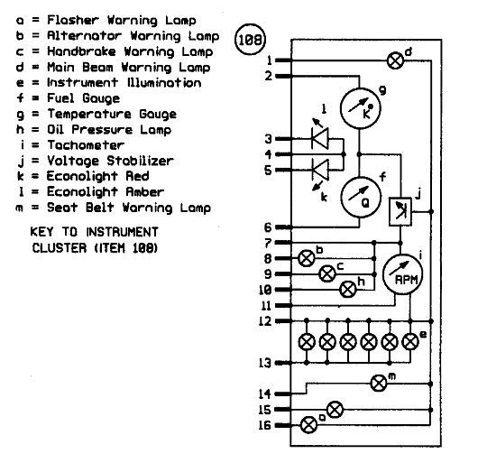
According to the Haynes manual there are/were 3 slightly different instrument clusters. The difference is small, the first ones had a single lamp for the indicator flasher, the next had a seperate lamp for right or left turn indicator and eventually a clock was added. Given the age of your donor your cluster should be the one with two turn lamps but no clock. A brief scan of all three versions indicates that the colour and purpose of the connecting wires remained the same. I am not familiar with diagram and loom that you have with you kit. The task that you (or your electrician) has is to match the wires in your loom with the function of the wires (or connectors) on the cluster connection plug. To help you do this I am attaching two diagrams, the coloured one shows which wires match which function on the cluster (by colour) and the second is more detail on which pin on the connector is related to each function. You need to identify which colour wire in your loom matches which connector/colour on your cluster. Sierra-87-89-diagram-16-inc-instrument-cluster.pdf
-
You had another thread "Pinto injection head identification", in that thread I posted a link to download a pdf tuning guide, the author of the guide is Des Hammil, perhaps it's the same manual that you have ordered ?.... anyway here is the link again .... when you see it on screen it looks like you can only view it on line, but hover the mouse on the text and a tool bar appears at the page bottom, in this bar is a "download pdf" option. https://procarmanuals.com/pdf-online-how-to-power-tune-ford-sohc-4-cylinder-pinto-cosworth-dohc-engines/
-
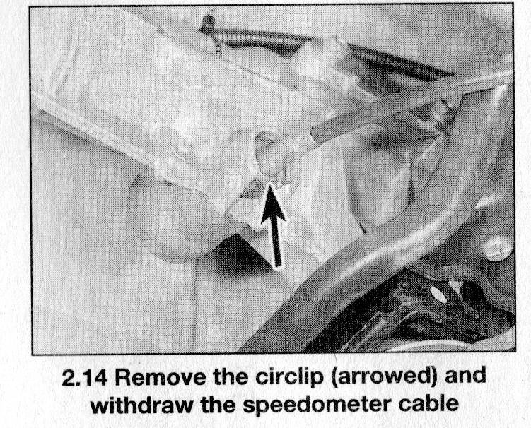
The simplest way is to buy the ford cable that connects the Type 9 gearbox speedo drive to the Sierra instrument cluster. You need to check that the speedo drive output is still there, it should be, but you never know, you cant miss it, it's on the driver's side of the gearbox not far forward of the gear stick and points down slightly. A circular hole with a female end in the middle, that a square section cable end can push into. Here is a photo from the Sierra manual. The circlip is likely to be missing, however these are available, along with a new cable, on eBay etc. The only other issue that you may have is how to route the cable from the gearbox to the cluster. As you see, it sticks out at right angles to the box, and almost certainly will not bend through 90 degrees to run down the transmission tunnel. On my car I have a hole in the transmission tunnel and route the cable on top of the drivers side floor in an arc to rise in the corner of the scuttle and then continue to the cluster. In order to do this you need to measure how long a cable you need, as the standard Sierra cable might be too short. I believe that a Mk2 Sierra cable (part no 6151472) is 2940mm long which should do. Oh! I just re-read your post.....a "universal speedo" .... I'd of thought then that a free standing, off the shelf GPS based speedo is your answer. Double Oh! I just realised something else ... you probably can't see this part of the gearbox because its hidden in your enclosed transmission tunnel ? ... in which case just to look at it might mean taking the engine/gearbox out of the car ..... maybe thats why it's not connected at the moment... the builder put it all together and then discovered that to connect the speedo meant taking the engine out. So another good reason for a GPS speedo.
-
Here is a link to free copy of the powertune manual, you can view online or download the pdf, it might be of help when you are considering what to do with your engine and converse with the pintp "specialists". https://procarmanuals.com/how-to-power-tune-ford-sohc-4-cylinder-pinto-cosworth-dohc-engines/
-
I have a copy of a Pinto tuning guide, in the guide there is a part about the inlet ports, it reads as follows :- The 36 to 38mm port diameter of all 2000 cylinder heads is optimally sized just as it comes from Ford and does not need to be opened out at all. In fact, it can be left in the as-cast state. The largest standard port size (38mm) is as large as the largest carburettor choke (38mm) that is normally used on a well modified 2000cc/2100cc engine. None of the Pinto cylinder heads, if fitted to their original block, really need to have their inlet ports opened out.
-
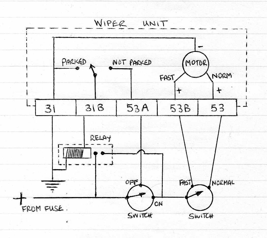
Okay, I have had a good poke around with the meter probes, and can confirm that connector 31 (leftmost in the photo) is connected to the motor body and the whole wiper mechanism. So the motor won't run without the body being earthed which means connecting connector 31 to earth. This means the my brilliant circuit diagram above is useless because it will cause the fuse to blow when the wipers are turned on from the park position. So I have given the matter more thought and have come up with a circuit that should work, using a relay. It still uses the two two pole switches, however could easily be modified to use a 3 position switch, where each position would give a connection. Anyway I have inserted the suggested circuit below. I realise you don't intend to use it, but I just couldn't leave this thread with a duff circuit diagram.