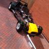
July 28, 201610 yr Ok so carried over from one of the other threads that I kind of hijacked.... thanks to Nigel for all the help so far! I've decided that I want to redo the electrics on the EXMO partly as the old sierra loom has definitely seen better days (soldered joints are failing apart) but largely to expand on my knowledge... there's a serious lack when it comes to electrical stuff - I can't see it working so struggle more than mechanical stuff. Point to note: my kit car is stored at the parents house in Cornwall while I am away working in the Midlands so alot of this is having to be done with some photos courtesy of Dad, research (Haynes manual) and a bit of hope/ dodgy memory! Current plan is to make as much of it as possible plug and play ready and to leave the engine electronics largely untouched, So the connectors I've chosen to use are super seal, I've ordered a range from 1-6pins so should cover everything I need. The fuse box from the sierra is pretty bulky and will hopefully largely be empty with the simplification so plan is to throw that and buy a smaller box, relay storage is yet to be finalised but thinking a nice mounting box from some Carbon Fibre would be interesting (aware it conducts so care will have to be taken). As Nigel confirmed I am planning on adding another relay for the headlamps so both dipped and main use a relay unlike the old loom. These will be courtesy of Car Builder Solutions. http://www.carbuildersolutions.com/uk/standard-relay-30-amp-4-pin-integral-mount Crimp connectors to be used are the standard spade type, alongside those shown below. These are thru crimps with an adhesive lined heat shrink to make them waterproof. The wires are still to be decided along with exactly what fuse ratings etc I will need. So first real job and steep learning curve is the wiring diagram, I'll be home for a week in August and plan is to get the wiring done... may well be a very ambitious plan! Please feel free to comment on the diagram / point me in the right direction! It's very much a work in progress with more stuff to be added as I go. Point to note is my sierra has the early stalks with the square hazard switch. Thanks, Suzanne
July 28, 201610 yr Would you not be better off getting the Cbs fuse board with relays and comes with a basic wiring diagram
July 28, 201610 yr The amp superseal connectors are great, however they only work well if you buy the correct crimping tool for them, I think I bought mine from www.polevolt.co.uk. If you use standard crimpers they bend the pins and they won't fit into the housing properly.
July 28, 201610 yr Hi Tractor, I have had a look at the cbs one and it looks good, however I quite like tinkering around with little bits and feel I'll learn more by making one myself, my plan for the fuse and relay box isn't massively far off the look of the cbs one however it should be a fair bit cheaper as well. Circa £30 I reckon - might not be as posh but it'll do the job and give me room to expand or decrease as required. Nice idea though! Hi Mcramsay, Yep luckily we use them for one of the projects at work so I've already had a little play with them and got one of the crimp tools. Thanks for the heads up! They managed to keep all of our circuits up and running when we were on a rather wet circuit at Croft last year - alot of the competition struggled in comparison. Edited July 28, 201610 yr by Tazza67
July 28, 201610 yr Love it. Ambitious but you can do it. LED front and side indicators can work but can lead to funny problems. Initial objection is you appear to have power to side lights and headlight relays going through S3. Blow that and you have no lights at all. So S3A, S3B and S3C so you would some lights in the event of a blown fuse. (Mine have six fuses because I can!) No dash repeater for turn signal shown but that can be as simple as a wire from the left flasher circuit to one side of the dash bulb and a wire from the right flasher circuit to the other side of the dash bulb. Earthing becomes through the inactive flasher side. Does this only work with standard incandescent turn bulbs all round? Cooking supper at the mo so will look again later. Nigel Edited July 28, 201610 yr by Longboarder
July 28, 201610 yr I used the fuse box in the link below and it's matching 4 way relay holder when I rewired my car. You can mount them separately or join them together for a compact unit. I also found it easy enough to replicate each individual system as per the wiring diagrams in the haynes manual. Link
July 28, 201610 yr Used those joints on MAN trucks on all the circuits. Even on delicate signal wiring. Easy to fit or strip with the right tools and super water tight. I also use the same bull it connectors and had no problems over the years.
July 29, 201610 yr Used the same 16 way fuse box and relay box as Steve. The more fused circuits the better in my opinion. The relay box is actually a 7 way mini relay one but only using 4 positions. I really wanted the 4 way version but this was bundled with the fuse box on eBay and got them both for about half the price of the fuse box.
July 29, 201610 yr The handbrake switch is a test switch for the brake master cylinder low level warning light. The low level mechanism on the master cylinder acts as the primary earth for the lamp and could be S6A. Tee'd in between the lamp and S6A could be S6B, the handbrake switch (or any other switch you choose to use to test the circuit whilst sitting in the car). Supply for the 'illuminated when on' rear fog light switch comes off the link wire S54 to 56, the headlights on link wire between the two sides of the column switches. (Thus fog light can't come on unless headlights are on and goes off if the headlights are turned off.) Next up is the dash board and all the warning lights. Nigel Edited July 29, 201610 yr by Longboarder
July 30, 201610 yr Thanks for the comments all! The integrated fuse and relay boxes look good - I'll have to have a dig around and see what stands out, so far I can't find them bundled together so £46 with postage. (In the process of buying a house so currently on a tight budget - this will be the last job before I hopefully get the house, which has a very long list of jobs to be done). Nigel, Yep your right on the tell tales I have slightly updated to account for the digi dash I'll be using (J6 is the digi dash on the wiring diagram and is effectively the tells): therefore I need to buy a few more tells to cover the IVA requirements. Thanks for the info on the handbrake switch, I knew there was a link to the master cylinder but hadn't figured it out. I presume the rear fog doesn't need a relay so have put that straight in for now. Hopefully the link to the latest diagram I have works... http://www.digikey.co.uk/schemeit/project/kit-car-2-65GJ530201N0/ Additions are: - Brake fluid warning light - Sight light tell - Digi dash + tells Thanks for the help! Suzanne
July 30, 201610 yr No dash repeater for turn signal shown but that can be as simple as a wire from the left flasher circuit to one side of the dash bulb and a wire from the right flasher circuit to the other side of the dash bulb. Earthing becomes through the inactive flasher side. Does this only work with standard incandescent turn bulbs all round? Nigel As Nigel surmises ?? the indicator tell-tale needs to be an old fashioned tungsten lamp for dash tell-tale to work with this wiring, think LED tell-tale would need one for each side or a bridge rectifier to ensure the LED is powered by the correct polarity.
July 31, 201610 yr Hi Florin, The digital dash has two individual tells for the indicators so as far as I am aware I therefore don't need to worry about them being led. These each have their own internal ground so polarity shouldn't be an issue. Thanks, Suzanne
July 31, 201610 yr Hi Jaimo, No unfortunately not been through the IVA yet... uni and grad job had taken alot of time over the last 4 years so it's had very little attention. Suzanne
Join the conversation
You can post now and register later. If you have an account, sign in now to post with your account.