Sparepart
 RHOCaR Member
-
Posts
351 -
Joined
-
Last visited
-
Days Won
14
Content Type
Profiles
Forums
Events
Store
Community Map
Everything posted by Sparepart
-
On an Exmo, be sure to examine the state of the front shock absorbers, this is because there are no off the shelf replacements, so fixing worn or shot ones could be expensive.
-
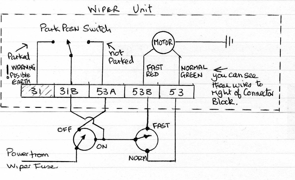
Actualy you are better off trying the simple swiitch setup. On close examination I can see a flaw in the more complicated circuit I proposed above. You can see that when the wipers are parked 31B is could be earthed. I show a connection from 31B to the ON pole of the first switch. This means that if 31B is earthed and the first switch is moved to the ON position a short circuit will occur and blow the fuse. This will not be a problem with the simple switch to power either 53 or 53B directly. I need to get back into the garage with my test leads.
-
Yes a simple switch from a suitably fused power source to 53 or 53B will give normal or fast motor speed. In it's original mounting in the Sierra the wiper motor and mechanism is fixed via rubber bushes to absorb vibrations, so if you have retained these the outside case of the motor will not be earthed. The contact 31 needs to be connected to an earth point. That would be the black wire in the wire list you posted at the start of this thread. Obviously if you use a simple switch the wipers will stop wherever they are turned off.
-
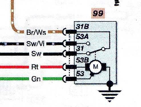
I am part way through wiring up my Sierra wiper motor, but have not finished yet due to other distractions, however I can share my plan if it helps. Firstly I include a snippet from the wiring diagram as fitted by Ford. This shows the original wire colours (Sw = black, German I think) The important thing is that as the motor turns it operates a switch that connects 31B to either 31 (parked) or 53A (not parked) I worked this out by monitoring the switch connections when the motor was turning. By the way avaoid trying to power the motor by connecting 53B and 53 to the battery, the motor runs very fast, too fast like this and would burn out. I now include my planned circuit, using two independent 2 pole switches to allow wiper self parking and two speed operation. The numbers on the connection block are in the same order as shown on your photo. Note I believe that connector 31 is earthed within the motor assembly so you must not wire any power directly to 31B because if you do a short circuit will occur when the motor arrives at the park position and the fuse will blow. This might be what is happening in your current wire setup. In the above the wipers operate via two switches, a "master switch" turns the wipers on or off which a second switch selects the speed. When the wipers are turned off and not already parked power from the Off pole on the switch is routed through the Park Position switch to turn the motor until it reaches the park position, and there disconnect. I repeat that I have not yet built this circuit, it's just what I plan to do if I get problems with the column switch and delay relay etc in the fuse box.

-
I have found the DVD's (2) and could make copies for you if you wan't, just message me with your postal address.
-
Yes, it's the vertical welds that are very hard to do properly. I am now doing a forensic check with magnifying glass. Originally I made a mistake by cleaning up the original welds with a non stainless wire brush. This contaminated the surface which then formed a layer of rust that disguised and "papered over" the cracks. I am beginning to wish that I had never looked so closely.
-
I also have built an Exmo from "new"... there are two VHS tapes, which I have had digitized, so have some rather large files that I have tried to upload into my cloud space and failed (so far), I can't promise anything, but I could dig them out of my archive and try to burn some DVD's, My PC is old and doddery (like me) so any media conversions take hours to process.... Also, you might see if Brumster still has the tapes that he was trying to give away about 18 months ago (was it?) ... but then you would need a VHS player (I threw mine away a long time ago) ... Failing that ... my Exmo is currently in re-build ... and Chichester is not a million miles from Seaford .... so you could come over and view the work in progress ... or just like IanS why not ask questions as you go along ... after all that is what a Forum is for and you might not have much left to do..... Warning though, I did NOT have to pass an IVA (just SVA with some allowed exceptions) .... there are other Exmo owners in the club that have passed IVA with an Exmo, their input would be more up to date possibly.
-
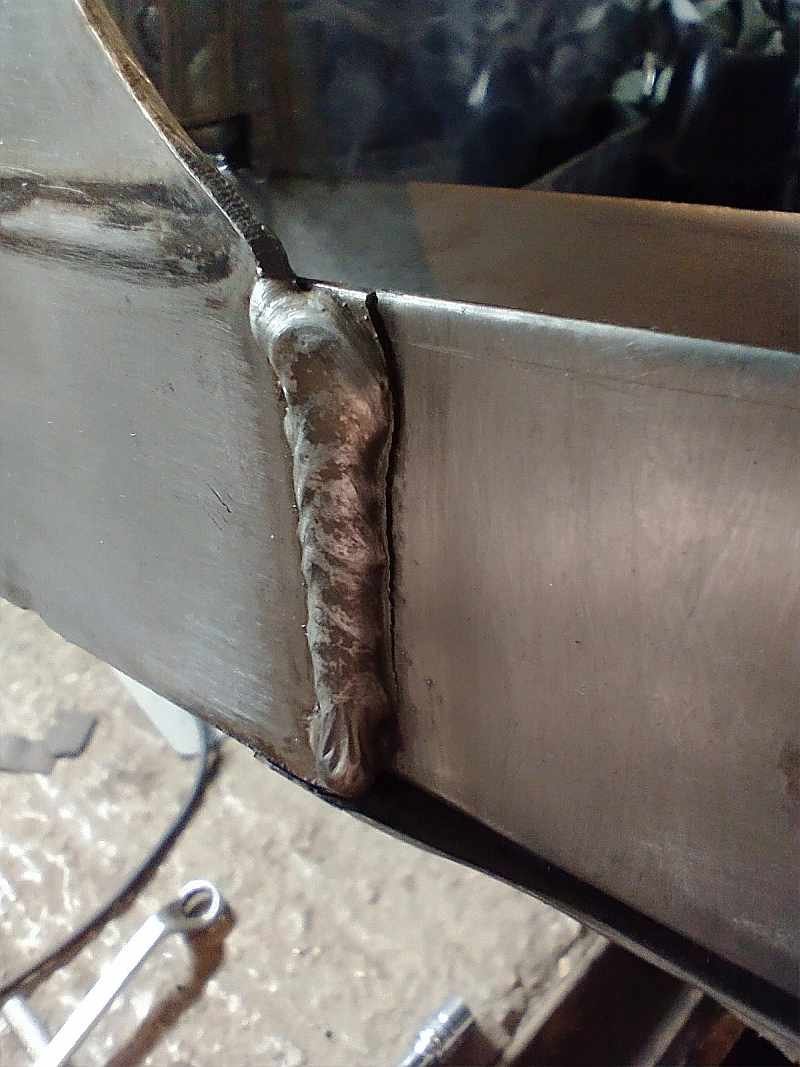
I'm rebuilding a stainless steel Exmo and hve reached the front. Previously in post https://www.rhocar.org/index.php?/forums/topic/3966-exmo-oxners-very-important-info/ cracks at the top of the front struts were reported. I now have discovered cracks, on both sides, in the "U" channel to which the track control arms are fixed. I attach a photo of the offside (driver's) side. It follows the weld which joins the leading edge of the outrigger to the U section cross member. To my eye its not in a place I would expect any stress from the suspension and it does not extend to the bottom of the section or across the bottom or up the opposite side. I think it might be due to a poor weld by RHE. The weld is very convex and has an excess of filler that might be causing an "undercut" failure, which appears because the base metal is thinned near the edge of the thick weld and brittle and snaps due to stress induced during cooling down contraction. At least thats what I am hoping. I will be welding a fix and keeping an eye on it after I get the car on the road. I thought I would log it here in case anyone else want's to check.
-
I found a very hazy slide show on you tube with the S7 biuld manual, page by page, its hard to read, might be clearer if a full screen capture was taken and then use "sharpen image with a photo editor. Here's the link https://www.youtube.com/watch?v=ElmcJ62w0qs
-
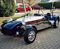
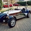
Yes, I agree with IanS, the top (orangy) ones would have been with the kit, same as provided with Exmo. The Exmo monocoque is a bit splayed out at the bottom so that the tub covers the ends of the rear subframe which can be seen on your photo of your S7. So as well as the rear arch in GRP there would have bee a SS "cone like" fairing that covered the end of the subframe. I'm not sure if it came with the kit or was left to the builder to make. Here is a photo of an S7 with the fairing.
-
I am considering your number 1 option at one stage, when I won't mind being off the road for a spell. The tough bit here would be removing the pressed on cap that holds the seal around the top of the strut. Although £320 quids might be required..... what is that nowadays, just a 3 or 4 of fill ups at the petrol station. Did Dampertech Dave give you a part number for what is needed ?
-
A picture of what you have would help. Is your rolling chassis of tubular frame construction or is it monocoque. If it's monocqoque then it should be obvious that you need the larger arches because thats the only way the area above the rear wheels will be enclosed. I have an Exmo, which I believe has a similar monocoque to the S7, and that uses the large arches that form the rear quarters.
-
I am afraid that I can't offer a solution, just sympathy. My Exmo has been under a tarp for 17 years before I started the rebuild. The bars that go through the oil seals were spotted with corrosion that has caused the chrome plating to flake and produce a rough surface which would quickly destroy the seals. Before refitting the shocks to the car I have carefully sanded and polished the affected areas, using a Dremel type tool with polishing compound etc. However, since the chrome is gone in these areas, its only a matter of time before some rust will set in. So I'm living on borrowed time. Leaking shocks will be an MOT failure at some point ..... so I too need to find a way to replace the shocks, not as urgently as you however.
-
Anyone available to finish fittings for reasonable price? (Essex)
Sparepart replied to Baba's topic in Fitting & bodywork
Nice video, a lot of work has been done to get it that far, on a quick glance, the car needs front cycle wings (do you have all the unfitted stuff, like wings, brackets etc?) Bonnet catches, front indicators, as said no need for windscreen. Needs wing mirrors and rear view mirror. Whats going on around the top edge of the rear drivers side wheel arch, it looks like something sharp there. we cant see the standard of work under the bonnet, things like fuel line fixing, electrical cable fixing, If not original wheel/tyre sizes, is the speedo now accurate? all this sort of stuff is well within the capabilities of a home mechanic, roll up your sleeves and buy a big tub of Swarfega. -
So it looks like it could be anywhere as long as its on something fundamentaly attached to the chassis. What I also meant to say was, that when the VIN was punched into the floor panel a metal "dolly" was placed on the underside, otherwise along with the VIN the panel would have a nice dent/depression. You might be thinking of an engraving, but if you do have a punched VIN on that cross member, that nice flat surfaced cross member, be careful not to create a dent. Sorry if this sounds patronising, it's not intended.
-
Please see my above post:- 7. The Stamped in VIN must be marked on the chassis, frame or other similar structure which is not easily removable, on the right hand side of the vehicle when viewed from the rear (see Notes 6, 8, 9 & 12). Your suggested place looks like middle front to me.
-
Have a look at the current IVA manual, section 18. (I some copy info below) , I took my car to a local garage and had them stamp the VIN into the flat floor pan near the drivers side edge. Also I had them stamp the VIN onto a similar thicknes piece if SS (2mm I think) which I then fashioned into a little plate that I pop riveted onto the bulkhead near the battery, so it is easily readable when the bonnet is off. Read the manual, the "main" plate has to be fixed pretty permanently, If I had a tubular construction I would not try and stamp the crved surface, I would stamp a plate and then weld it to a piece of the tube on RHS (as viewed from behind) near the drivers thigh area so that it can easily be uncovered for inspection, like pulling a flap of carpet back. 18 Statutory Plates 7. The Stamped in VIN must be marked on the chassis, frame or other similar structure which is not easily removable, on the right hand side of the vehicle when viewed from the rear (see Notes 6, 8, 9 & 12). 8. The Stamped in VIN must be placed in a clearly visible and accessible position by a method such as hammering, stamping, etching (metal chassis) or embossed, moulded into the structure (glass fibre or carbon fibre chassis) so that it cannot be obliterated or deteriorate. 9. The VIN number must consist of 17 digits with the information shown in a single line (except for mass-produced vehicles where the use of two lines is permissible) (see Note 7). 10. Capital letters and numerals must be used for the VIN 11. There must not be any gaps large enough to insert extra characters between the characters for the VIN shown on the manufacturer’s plate or stamped into the vehicle (see Note 4). 12. The Vehicle Identification Number on the manufacturer’s plate must be marked in characters at least 3.5mm high. 13. The characters on the manufacturer’s plate (with the exception of the Vehicle Identification Number) must be at least 2 mm high 14. The characters used for the VIN stamped into the chassis, frame or other similar structure must be at least 3.5mm high. 15. Use of the letter I, the letter O, the letter Q, dashes, asterisks and other special signs are not permitted (see Note 10)
-
Me too, I'm in process of replacing mine and have chosen the standard rubber bushes because they are less expensive than the polyurethane sort. Also all the other bushes are standard rubber, so whats the point in having just one pair stiffer, won't it just pass stress on to the softer parts?.... weakest link in a chain etc.
-
WoW! that is good value. I bought mine with the original kit in 1996 (24 years ago) for £22 AND they did not include the anti roll bar bushes that are circled in Kermit's picture, so £35 including the anti roll bar bushes is a real steal.
-
Also you could look to see if the head is for unleaded. Normally, 2.0 litre heads with unleaded valve seats are stamped with 'P', 'PP', 'R' or 'RR'. Unleaded I/D for Pinto next to number 4 spark 1.6-- M,MM,N or NN 1.8-- S or SS 2.0-- P,PP,R or RR I can't remember where I got this from.
-
Take off the air filter. When cold you should see the choke butterfly is flat across the main inlet tube. As the engine warms up the butterfly should rotate and open up the inlet, eventually becoming almost vertical, fully opening the inlet. If this does not happen then the fuel/air mixture will gradually become too rich as the engine warms causing rough running and eventually the engine stalls, usually with a strong smell of petrol in the engine bay.
-
Without knowing what kit you have it's hard to help. The rack on my car comes from a Sierra and is bolted directly to the cross member, same as it was on the donor Sierra.
-
If there was/is a problem with the choke giving a rich mixture then you should have lots of smoke just before it cuts out as the engine drowns. If there is the opposite problem, i.e. a fuel supply problem (blocked jet, blocked line, fuel pump failing when hot etc) then after turning over and not starting, whip out a plug and see if its wet with fuel. If it's dry then fuel supply could be an issue. However, by the sound of it, you get smoke when its finally starts, probably not a supply problem, but could look at plug anyway. Also when it turns over and doesn't start you could whip out a plug and with the lead attached check if there is a spark when the outer part is touched to earth with the engine being turned over (you need two peaple for this). You need to see a really good spark, because when the plug is in situ and under compression a spark is harder to produce, so a failing coil could produce a spark, but not at enough voltage to work in situ.
-
It would be unusual for you to have a wiper arm connected directly to the motor. You probably have one of two mechanisms, most likely hidden under the scuttle. Obviously both types use an electric motor. In one arrangement the motor drives a crank lever that moves a solid bar back and fore, the spindles for the wiper arms each have a solid bar conecting to the one driven by the crank, it's all quite a sight to see in motion, also takes up space under the scuttle because all electrics and anything else needs to be kept clear of all the moving parts. The other sort, is much more refined, the motor also has a crank (small) that drives an Archimedes screw cable (encased in a sheath) back and fore. Anywhere along the length of this cable a spindle drive can by inserted where a small peg inserted in the screw will cause rotation as the screw moves back and fore, two such drives are inserted, one for each wiper. This type is much more compact and does not endanger surrounding fittings. Well done if you have stayed awake long enough to read this far. Most kit builders use this second kind, it is what was originaly used by BMC cars, Austin, Morris etc and most notably on the original Mini. If you currently have this type then the wiper arm is a push fit on to a splined spindle shaft header, you won't have a nut, you just pull them off, they can be hard to remove. So as pintogogo says, if you do have this Mini type of wiper then you should find what you want at the link below. https://www.carbuilder.com/uk/windscreen-wash-wipe
-
Thinking of buying a kit car? Read this first.
Sparepart replied to richyb66's topic in Kit car related
I am thinking (always risky), my car is "C" reg (1985), however just like for IVA, the V5C shows date of first reg as January 2000 (SVA date). I wonder if I can now purchase a personalised number for any year up to 2000 (that would be a V reg car) .... it would give me more choice of numbers ... I'm assuming that when a different reg is put on a car they only check that you are not trying to put on a plate thats for a year newer than the date of first reg?