Sparepart
 RHOCaR Member
-
Posts
351 -
Joined
-
Last visited
-
Days Won
14
Content Type
Profiles
Forums
Events
Store
Community Map
Everything posted by Sparepart
-
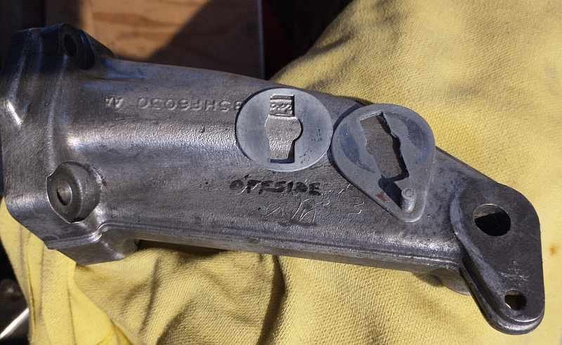
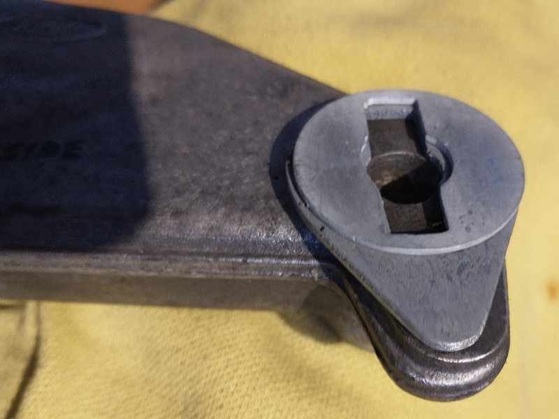
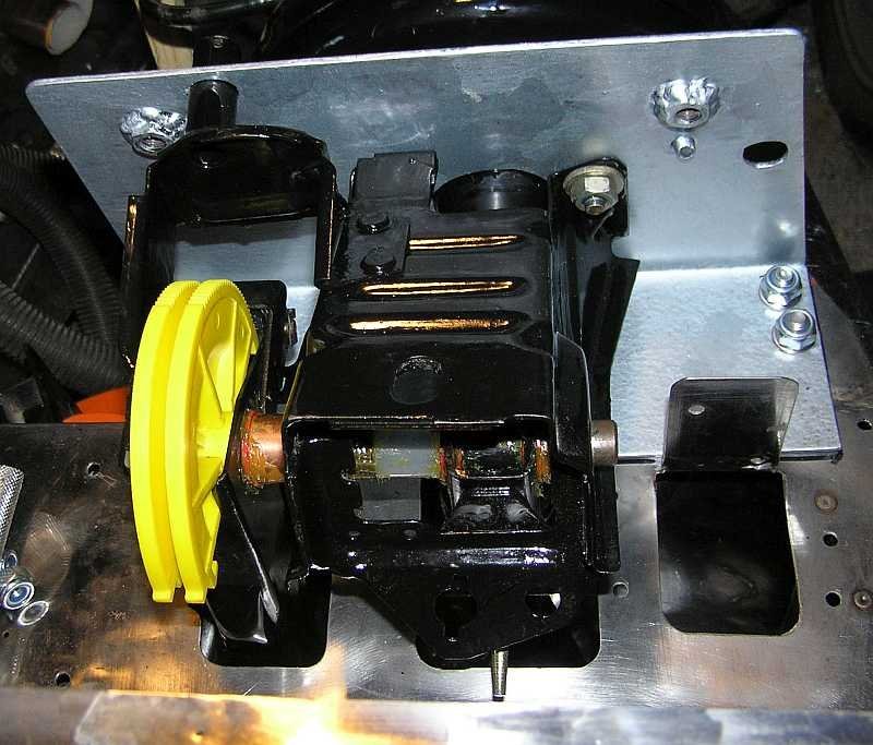
On the Mk1 Sierra (at least mine) the engine support arms do not have a slot. They use a special washer and spacer that fits over the bar in the mount and slots into a hole in the support arm. This means that there is no twist on the bolt in the rubber part when tightened or loosened. I attach two photos below that show the washers and the arm.

-
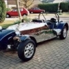
There is nothing special about your Ford Pinto engine, so just Google for advice on starting an engine for the first time after having been silent for a while, it's simple stuff like making sure the oil is clean and up to level, water in the cooling system, clean fuel in the tank and pipework to the carb etc..... take the plugs out and turn it over on the starter first see if oil pressure is enough to turn off the warning light.. check you even see a spark at the plugs, check that the timing belt is okay. As for the missing master cylinder, your Sierra servo doesn't look too good, rather than trying to get a Sierra master cylinder, you might consider ditching the servo and fitting a Ford KA master cylinder. Members have done this. Just use this sites search facility and search for "ford KA" (in quotes) and you will see the posts relating to this. As for identifying which 2B you have check out the page we have on identification at https://nw.rhocar.org/htm/identification.htm . The 2B build video is on Youtube at https://www.youtube.com/watch?v=DNA1Zs8jY_I
-
This is a suggestion, ive not tried it. Firstly use a long straight edge, say length of baton between scuttle top and nosecone edge to measure how much clearance you actually have. Then look at at thin universal pancake filters, like https://www.ebay.co.uk/itm/311892226985 to use. Such a filter could even be made thinner by trimming the sponge and cage, but obviusly too thin will strangle the carb. The other challenge will be to find a way to mount it on the carb. You could cut a round hole a bit smaller, say 20mm, than the inlet diameter, then cut lots of radial slots round the circumference, 10mm deep, then bend each out at right angles. This would let the filter base slot over the carb inlet with a jubilee clip around the all the bent down bits to fix it to the carb. Perhaps some tape around this would then make an air tight seal. The filter could be mounted upside down so that the dome nuts are underneath, leaving a totally smooth upper surface.
-
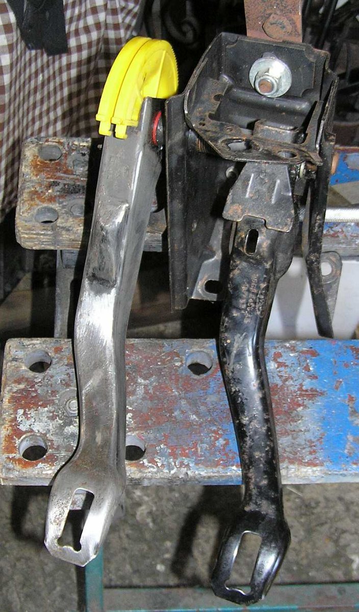
Bit late to this topic.... I attach a couple of snaps from my car. The second is the standard pedals, to see the standard spacing, yours look to have an offset brake pedal, but that could be perspective. The first is from above with the pedals installed. You see that the throttle is seperate, not installed, so could be moved easily in all directions. What is not easy is changing the height or spacing of the clutch/brake pedals. The clutch quadrant position is fixed by the release mechanism in the cable guide, and the brake pedal top by the alignment of the master cylinder rod. Moving the whole assembly up is theoretically possible, with spacers, but the whole top cover (not shown) would need to be raised, all the brake pipes extended, and then not so high as for the servo or fluid reservoir to hit the bonnet. Lowering the floor and/or altering the pedals is going to be easier, although shortening pedals will of course alter the leverage and range of motion somewhat, e.g. shorter clutch pedal would be harder to release smoothly.
-
Oh, just look at the S7 build manual, (I have an Exmo) and there is a small difference, the routing of the S7 cable looks to be through the sloping panel as shown in the build manual that I attached before in a different thread https://www.rhocar.org/index.php?/forums/topic/50972-s7-handbrake-cable/#comment-413125
-
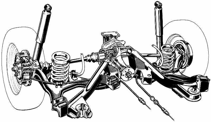
Have a look at this diagram, of the Sierra rear subframe from above. See, the cable route is pretty much symmetric, left to right. From the wheel backplate on top of the trailing arm and then through a hole in a flat plate part of the subframe really close to the pinion UJ (not shown here), so you have to imagine the prop shaft between the loop in the cable, out of frame bottom right to the pinion flange (shown). On the Sierra the nylon adjusters use a bracket from the body, but on your car the adjusters use the aformentioned holes in the flat part of the subframe. Out of frame there is an exposed loop of inner cable that goes through a metal yoke. The centre of the yoke is attached to a single rod that goes to the bottom of the handbrake. When the handbrake is applied the yoke moves forward and tightens the cable, if the yolk is properly lubricated any difference in L/R tension will be equalised by the cable slipping through the yoke. Because the cable is shorter than the one shown here, the yoke will be really close to and just above the prop and UJ, just inside the hole through which the prop appears from the transmission tunnel. If you use the "cut the cable in the middle" method of fitting then whatever you use to rejoin the ends has to fit in this restricted space between where the cable comes through the subframe and the yolk, without fouling the UJ or preventing enough slippage through the yolk to equalise the R/L tension. If you shorten by removing one of the end pips, then you have to be very careful to pre thread the items along the length of the cable before you weld on the new pip. Hope this helps.
-
Something in your description of where the wires go, does not sound good to me. Unfortunately you don't say which wire is + (I'm assuming black) and so green is -ve which would match the colours used in a standard sierra loom. The way a coil works is that with ignition on, and engine not running (and points closed if you are using points) then the +ve should be live via the ignition and the -ve should run to earth but not directly, it must run to earth via the ignition module (or points). In this state the low tension windings in the coil are energized and there is magnetic energy in the coil core. When the engine is running, the ignition module (or points) suddenly disconnect the -ve from earth, this causes a suddend collapse of magnetism in the core, and the energy is dissapated in the high tension coil, giving a high voltage pulse that is used for a spark. The dissconnection only last a short while, so that the coil can recharge with energy for the next spark ... and so on. So ... if the -ve connection on your coil is directly connected to earth, there will be no interruption in the circuit and so no spark. In the Sierra loom the black comes from the ignition switch, the green runs to the electronic ignition module, which then connects the coil to earth but intermittently disconnects when a spark is required, depending on all the other inputs to the ignition module.
-
Just browsed the parts catalogue, I think you need to purchase a Ford part that you will find by either using the number 1644433 or the code 83BB2A603AG, just put "Ford" in front and search with your favourite search engine should pull up a Sierra MK1 handbrake cable assembly..... then find the best price/quality etc.
-
I think that you need to buy a Sierra handbrake cable MK1 or Mk2 probably ok, because it will need to be shortened. There is no "off the shelf" part I am attaching a pdf of the three pages covering the handbrake, from the build manual. It is just about legible. S7-Handbrake-Build.pdf
-
I am wondering if you are checking your car against the IVA manual ? In the section on seat belts, there is the following:- Note 2: A suitable single bolt fixing of adequate strength would be, for example, a bolt of at least 11mm (7/16") diameter of grade 8.8 (the grade may not be shown on a bolt produced for a seat belt anchorage). Other bolt fixings may be acceptable providing they are of equivalent strength. Two adjacent seat belts may be secured by one bolt. In this case consideration must be given to the additional loads on the anchorage Just in case you have not looked at the IVA manual, HERE is a link to the current version (today 2023-10-14) on gov website.
-
Potentially there are three areas that might be preventing the drum from coming off the hub. One is the edge of the drum around the hub, in your photo this is the start of the rusty bit, the hub being black paint. Wire brush the rust off and apply penetrating oil (WD40) to the joint area. The next thing might be the wheel studs, which the drum has to slip over, again wire brush the base of these and apply penetrating oil. The third area is harder to free. The brakes are self adjusting, each time the the handbrake is applied, see the manual. It is possible for the shoes to be tightly sitting in a "trench" formed by wear and rust build up on the inside drum edge, stopping it from coming over the shoe surface. You can tell this is the case, if when you try to lever the drum off, carefully with a broad screwdriver or tyre lever between the drum edge and backplate it seems to be free at the hub and wheel studs but keeps springing back on to the hub when you let the lever go. In this case you should try releasing the shoes as described in the manual. My copy does not just say "remove the drum" there is the following "it is possible to release the automatic adjuster mechanism by inserting a screwdriver through the small hole in the drum and pressing down on the ratchet (see illustrations). .(5.5b)..... but I dont see a small hole in your drum, look for it. Your brake adjuster looks to have the locking mechanism missing, someone has put a lump of something there to stop it unwinding itself. Again look at the manual especially at the "hand brake equalizer" see figure 29.3. The cable has to slide through here easily to even out tension between both sides. And like IanS says the cable will have been shortened by cutting a piece off and fixing a new ferrule. The build video shows how to drill a hole in the center of a piece of bolt thread, put the cut end through and crimp using a cold chisel. Something like this might have popped off and the cable can now just pull out from the backplate on one side.
-
Just did a very quick search, loads of hits, this one most recent and looks to answer your questions. https://www.rhocar.org/index.php?/forums/topic/39046-cooling-system-diagram
-
Yes that certificate is the SVA approval, same as for mine in January 2000. The SVA included an emission test, Limits were %CO by vol 3.5 and HC ppm 1200. The engine is/was as per the Sierra donor, twin choke downdraft carb (Weber DFTH 30/34) and no catalist. The actual tested values were 0.34 and 745 respectively, well within the limits. I have had several MOTs since, some have re-measured the emissions against these limits and earlier ones just didn't test, I don't know how they managed to do that and I didn't ask.
-
The letters LP on the engine serial number indicates that the block was manufactured August 1990. The link below, is to an online copy some of the Haynes Manual, some chapters are missing. The Chapter on the Pinto (SOHC) engines is present, it does cover a lot of engine rebuild and specifications of parts etc however it's not a detailed workshop manual. It is more like a guide in places. https://www.leschroniquesdegoliath.com/wp-content/uploads/2018/01/Ford-Sierra-Service-And-Repair-Manual-GB.pdf
-
I have attempted to make sense of the IVA Manual sections 20 - 30. There is nothing about any lamps having to be mounted vertically. The requirement for all the lamps is specified by the "angle of visibility", both horizontal and vertical. Also the lamps cannot be tilted so far that less than 50% of their apparent surface is visible from anywhere in the required angle of visibility. I guess to be absolutely certain a lamp is acceptably mounted one would need some trignometry and a measuring stick vertically at a known distance from the lamp. Mark the horizontal height of the lamp on the stick and the distance above that gives the correct angle. Plonk the stick vertically on the floor at this distance and look towards the lamp from just behind the stick. More than 50% of the apparent surface of the illuminated lamp then must be visible at least from the bottom mark all the way to the top mark. Oh yes, you must then move this stick around in an arc to check that it satisfies the vertical visiblity at all points of the horizontal requirement. This is easy because you can fix the bottom mark on the stick to the bottom of the lamp and just move the stick around keeping the string taught. Sounds complicated ... but a low tech measurement. Oh yes, there is all the other stuff about height of lamps and distance from the sides of the body ... thats easy. The only place I had trouble with the old SVA was the front indicators, on the EXMO the build instructions were to place them on the suspension outrigger below but closer together than the headlights. This position failed the horizontal visibility check, as the nose cone obscured the full extent of the angle (45 dgrees I think). Anyway I was surprised as to how far out of the nose cone sides I had to mount them on stalks. Iv'e seen cars since that must fail this test, my guess is that it was changed as soon as SVA/IVA was passed.
-
I will also be needing to replace the shock absorbers on an EXMO at some time in the future, they are okay at the moment. The last postings regarding this, I believe, were in the thread https://www.rhocar.org/index.php?/forums/topic/27038-exmo-suspension/page/4/. Might help.
-
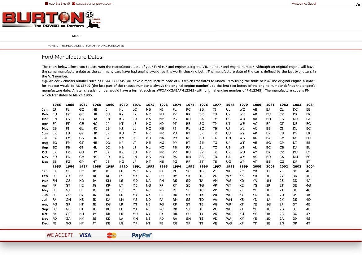
This is an old chestnut. I have picked up lots of scraps of info from this and other forums over the years. In my amalgamated text file I have the following line. 'I' OR 'L' stamped next to number 4 spark plug hole= a leaded head most likely to be 1979 - 1982 in age. Now you are wondering about the age of your engine. Find the engine number stamped on the offside, near the front, should also match the V5 document. It should start with two capital letters. Then look at the attached screen grab from Burton Power to find the month and year of manufacture. For example my engine number has FR (June 1985) .... notice another FR in Oct 1966 .. cant be for a Pinto though. Oh! yes, also this assumes that the cylinder head and block are the original pairing.
-
All the comments on rear would be the same. Car on level, to just get a rear wheel off on one side use a scissor jack longways and thin piece of protective ply wood as close to the hub end of the trailing arm as you can get. Wheel will soon come up enough to remove, suspension is still compressed. To get both rear wheels up, use a small trolly jack under the differential with again ply wood to protect the casing. If you use a fixed lifting jack here then dont prevent the front wheels from from moving back, otherwise the jack might start to tilt. This takes a longer lift because the suspension has to travel fully down before the wheels lift, and I think a little postive camber develops. On the Exmo you have to be careful because the original design just used some nylon rope to stop the trailing arms reaching a point where they foul the static "yolk" and the springs pop out. If you have coilovers then I assume your car will rely on the full extension travel stop of the shock absorbers to prevent a similar thing happening. Depending on your jack you might need to drive the rear up on some strips of wood to get enogh clearance under the diff. In this position the car will not really be safe to do anything really because its like a wobbly triangle. So to make it safe I do what is described above, and use a piece of 2x4 wider than the body and place it just forward of the rear subframe, just in front of the thin piece of SS that sticks vertically down. I then put axle stands under each end of the wood. As for the front then I don't know for a series 3, probably one wheel up for a wheel change would be somewhere like at the inner end of the radius arm.
-
I think you will find that the manual attached above by dandan62 is the one issued for the S7. I say this because the tiny section on rear suspension indicates the use of the donor springs in the same place on the trailing arms ( I think the series 3 has coilovers at rear) and right near the end there is a copy of an insurance quote for the vehicle from Adrian Flux dated 24/6/93 (bit blurred) "in respect of the Robin Hood S7". Having said this, however, there is a lot that is the same in this manual for both S3 and S7 (and Exmo) the differences will be mostly in the front suspension design. I think that from the Exmo on, there were only build videos on VHS as IanS says.
-
This is very close to me, a short bike ride even ...... but alas, I will be trail running down at Dell Quay with BBQ after. Any way the EXMO is not on the road yet, the engine is at Banda Engineering in Portsmouth, just been reconditioned, awaiting collection. Enjoy your breakfast.
-
Just to be clear, in the image, the open hole below the coolant drain plug, is an oil LEVEL sensor position, not pressure. It was fitted on high end Ford models with this engine. The normal level sensor is of course the dipstick.
-
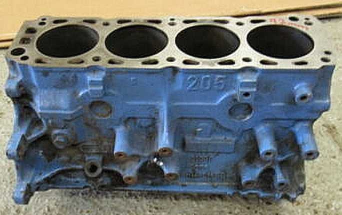
I attach a photo of a 205 block, exhaust side, there are two holes, the higher (here with plug in) is the coolant drain plug, the lower hole (sensor missing) is for the oil level sensor which was fitted on the Ghia versions of the Sierra. If you still have the Ghia loom complete there will be a plug for the sensor with wiring to take the sensor signal to the "Auxiliary Warning System", this was a swish display just above the gear lever on the dash that had all sort of warning lights, door ajar, washer fluid low, brake pad wear, fuel range ..... etc. I'm guessing that you don't have the AWS, or even the Ghia loom..... If it is the oil level sensor that you are looking at, it will have been left there becase it blocks a hole out of which oil will splash when the engine is running.
-
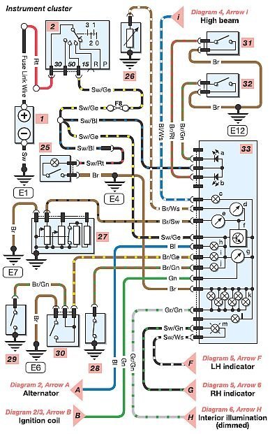
In the attached diagram, d and e are the temp gauge and fuel gauge, you can see that they both draw power from f, the voltage stabiliser. This power then runs to earth via the sensors, 27 is the fuel gauge sender unit and 26 is coolant temp sensor. As you can see it is only these two gauges that use the stabilised voltage, so if the stabilser fails these gauges will malfunction. You could also test that power is getting to the stabiliser, check F8 in the fusebox, and for power on the Black/Yellow wire to the instrument cluster, with the ignition on. Actually if there is no power on black/yellow other things wont work, like the oil pressure warning light (j/28), so if this is working there should be power to the stabiliser.
-
I bought an Exmo, it has a SS tank, and as dandan says the RHE tanks of this era were SS, just plonk a magnet on your tank to confirm. In which case welding on the alloy neck is not possible. You might consider bolting it on though. I see that Burton Power sell various sized pre drilled and nutted rings that can go inside the tank. They are designed to go with their Aero filler caps..... so not in the tank in their application ..... but they have welded nuts and are "horseshoe" type so could go inside a tank. The link below is to their catalog page, at the bottom, I think the ring for the 2.25 inch cap might do. You can buy a sheet of nitrile/cork gasket material and cut your own gasket. Anyway just a thought, would need more detailed investigation. https://view.publitas.com/burtonpower/2023-catalogue-pages/page/58
-
Since I have been totally rebuilding, I have removed the tank and washed it out with detergent, so I did the flange work during this, all debris was washed out and also vacuum cleaner round interior of seams. Now, if you are going to buy the Ford fuel tank grommet, I don't think that you need to pay the £45 quids that you mention. I did some deeper investigation. If you start with a Ford parts catalogue (link below) you can find that a Mk1 Sierra fuel tank grommet has two possible reference numbers, i.e. 72GB9072AB and 1492183 and also you can see that this part was fitted to other Ford cars, Granada, Escort, even Ka I think, anyway it's the part number thats important. Then if you Google something like "Ford 1492183" you will see that a grommet can be obtained for around £16. Below I include a link to the online parts catalogue I used (Select Sierra Mk1, and then scroll down to the section on petrol tank, then look at the diagram and see the grommet item number 10, then follow the link on the right to the part information that shows description and other Ford cars to which it was fitted). Below there is also a link to one of the £45 offerings, and you can see that in details they show the part number as just "149" which I think must be on purpose to obscure the full part number from web search...... or am I being cynical. Also a link to a cheaper provider of the same part. I hope this helps. https://www.fordopedia.org/ https://www.ebay.co.uk/itm/125331672244 https://www.ebay.co.uk/p/1709767924