Sparepart
 RHOCaR Member
-
Posts
351 -
Joined
-
Last visited
-
Days Won
14
Content Type
Profiles
Forums
Events
Store
Community Map
Everything posted by Sparepart
-
On an episode of Wheeler Dealers (US) Ant Anstead manages to shear 3 bolts he can be seen using a TIG welder to carefully add metal to the sheared end until there is enough to grip and turn. In his case the stumps are still a little proud of the surface. However rather than throw away the flywheel you could try this technique. What can happen ? if you are lucky, the weld will only take to the stump of the bolt because of the big thermal conductivity in the main body of the flywheel the bolt metal will melt first. If you are unlucky you might as well just really fill the hole with weld and then try drilling it out again, starting with with a very small diameter drill through the centre. Could use remaining bolts to mount the clutch housing to accurately center the drill in the housing hole. Here is a link to Ant's efforts. https://www.facebook.com/DiscoveryUK/videos/ant-removes-broken-studs-wheeler-dealers/250798119707281/
-
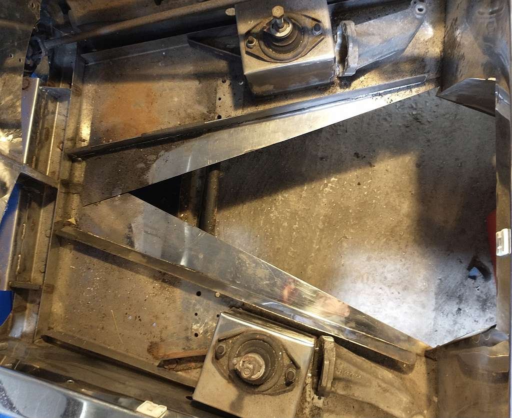
I am soon to get to the front end of an Exmo rebuild. I have found lots of good advice regarding the front suspension mounts and tie bar conversions. I have been cleaning some of the leaked engine oil and gunk from the "trays" that carry the engine supports. Originally these trays were free floating and needed to be aligned to get the engine positioned correctly. Now of course they are bolted in postion and will stay where they are. The panels underneath these trays is fairly thin SS, and they extend out towards the sump from both sides forming a V shaped hole that is just wide enough for the sump. If you built an Exmo you will probably recognise what I am talking about. I have attached a photo below. Anyway, to get to the point!. I am wondering if anyone has modified these thin sheets ? perhaps to cut them back and fold them up to the edge of the trays and weld them there ? I think that this might be stronger that having them flat as they are now. If you grasp the edge they are easily flexed and cant be adding much support. What do think?.

-
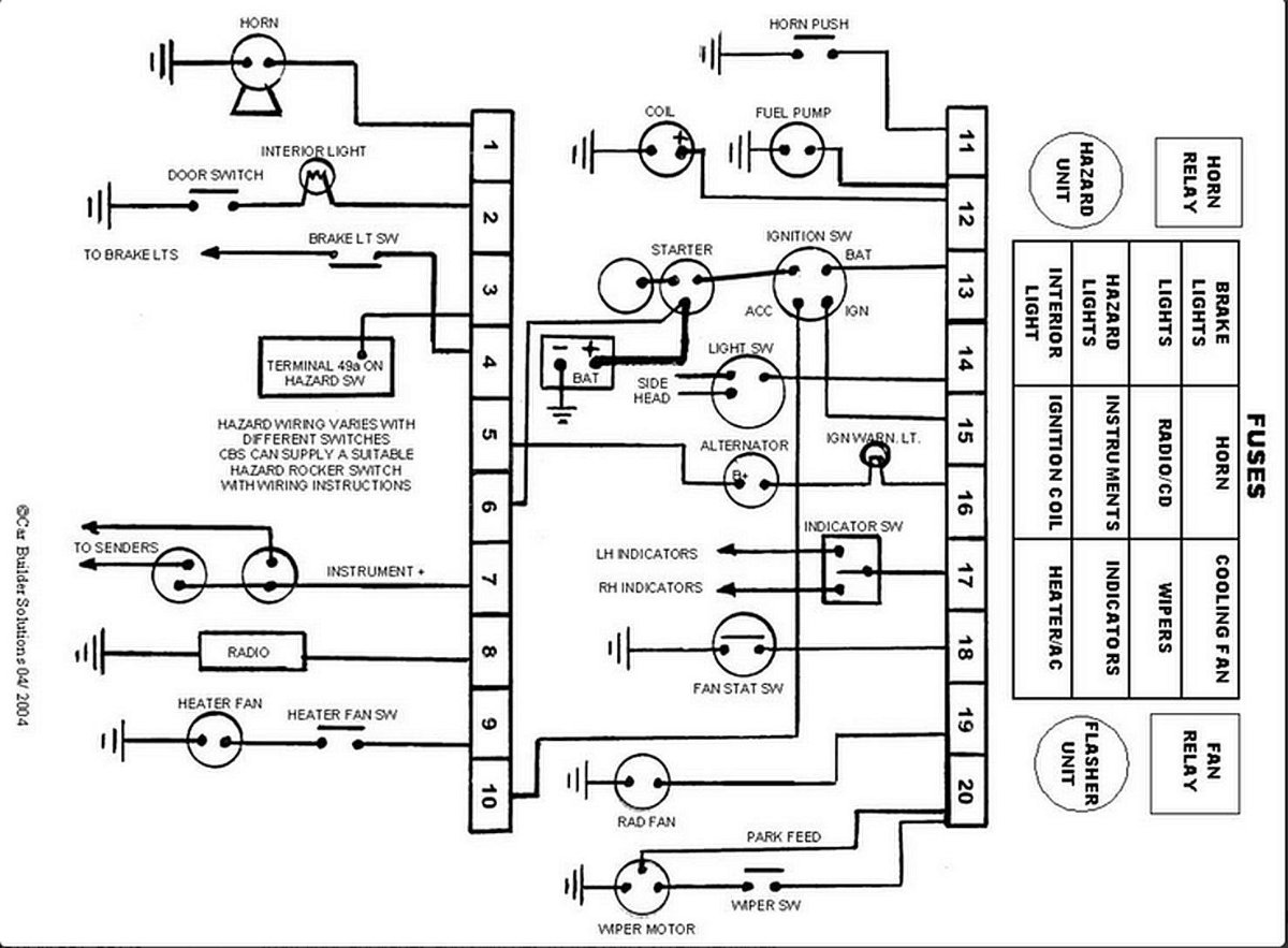
Is the diagram below what you are talking about? The wires that you describe are not what I would have expected, however I can see that they might make some sense. There are 3 components at play here, The Battery, The Alternator and The Starter. Electrically, the positive terminals of these three are all connected together. In the above diagram you can see that the battery positive is connected to the starter and then there is a wire from the starter to terminal 6. So terminal 6 is the source of +12 volts for everything else. The Alternator is generating 12 volts and must be connected to the positive terminal of the battery. Using the above circuit the only way that the alternator can feed the battery is for terminal 5 and 6 to be connected. This then would be electrically similar to what you describe, i.e. a wire from 5 to the starter and then on to the alternator. So the Postive terminal on the starter is acting as a common positive terminal. What is most important here is the thickness of the wires, as the starter will take high amps from the battery and the alternator will generate high amps into the battery. Most cars have a seperate very thick, unfused, wire from the battery to the starter, so the postive terminal on the starter can be treated very much like the positive terminal of the battery, it's just that the starter is not as accessible or convenient. Hope this makes sense. Just a thought, perhaps the intention was to have the battery mounted away from the engine bay, at the rear ? in which case it would make sense to use just one thick cable from the battery to the engine bay and use the starter terminal as the main positive terminal.
-
Just Google "classic mini sealed beam headlight" they are available online from many sources. Also you might be interested in a conversion kit that has recently been discussed in another thread. https://www.rhocar.org/index.php?/forums/topic/49540-headlight-wiring/&do=getNewComment
-
I am looking at the CBS 12 module and thinking how it might work with the components that you will have on the Sierra based car. At the same time I am looking at the circuits on the original fuse box. I grant that much of the original fuse box is devoted to features that are no longer present (e.g Headlamp washer relay, rear wash wipe etc). It seems to me that the CBS 12 is almost too "bare bones", having an absolute minimum of relays and fuses. You might find the CBS 12 is a weak link in having more sophisticated features. For example there is no provision for an intermittent wiper relay, or if you want to run the headlights off a relay to avoid thick wires running to/from the dashboard. I am guessing (just as you have) that the intention was to have the fuel pump powered only with ignition on and to do this via an ignition activated relay. In any case you may well soon find that you have need for another fuse or relay, so I would keep the "extra" module.
-
Hi Kyle, I am sure you will find that there are many people in this "community" who will be happy to help (me for one), most members will have fought with a loom or two. Of course your aim is to have a perfectly operational and reliable electrical system on your 2b. I think you need to put us in the picture as to what is your starting point ? In particular try and identify the origin of the loom. Was/is it from the donor car ? or was it purchased did you uncle leave any paperwork?, most builders keep receipts even if only to cry over how much the car is costing.
-
I agree, the condenser/resistor/suppresor unit is not needed if you have contactless (no points in distrubutor) ignition and a 12 volt coil. It is used to prevent voltage spikes in the wiring loom which can be the cause of "Noise" on a radio, crackling noise that increases in frequency as the engine revs. I will still try to fit one on my car, I do not have a radio, however I wonder how far away the electrical noise extends. Might it affect nearby radios or Tvs and annoy others ? .... something that could be tried ..
-
On my sealed beam units there is a clear circle on the reflector below the main fillaments. The big connector that plugs on to the three pins (for the main and dip and earth connection) has a a small bulb mounting attached so that the 12 wat side light, with it's own small reflector is held right against the clear window in the reflector. Thus there are four wires involved. It seems to me that you do not have the small reflector etc. https://www.autoelectricalspares.co.uk/bulb-holder--wiring-loom-angled-with-pilot-light-window-for-sealed-beam-headlamps-2613-p.asp
-
I don't have sidescreens or doors (yet).
-
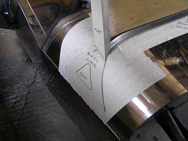
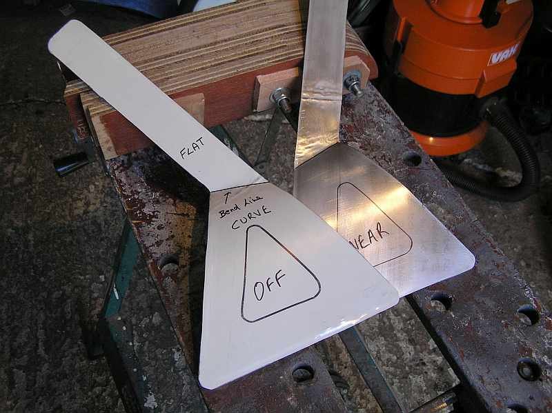
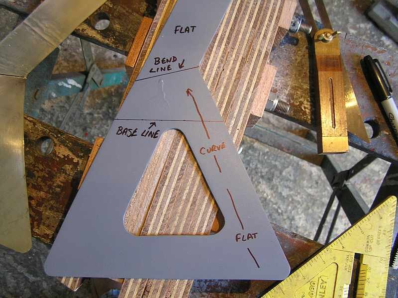
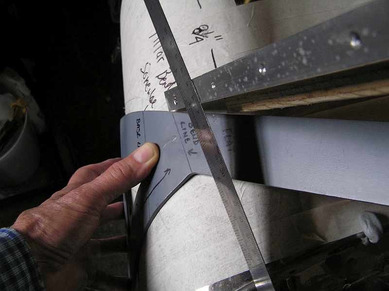
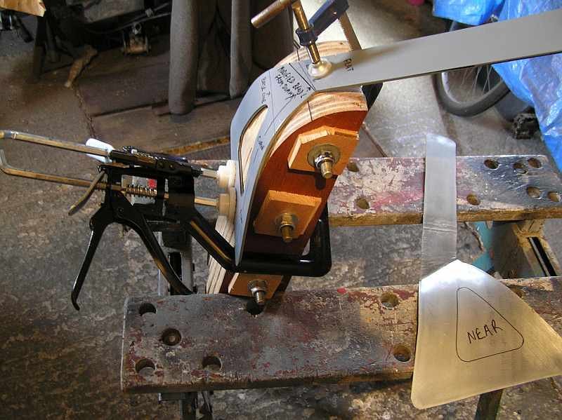
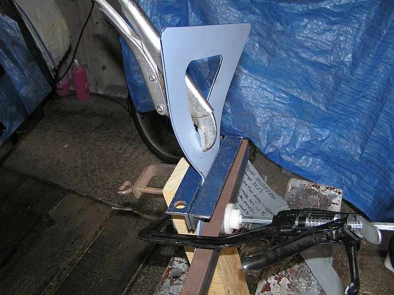
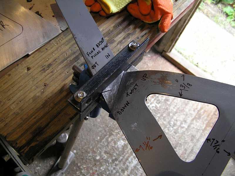
Here are a series of snaps, that shows the path I followed. As you have found the brackets are thick and hard to bend. So I started by making copies in thin mild steel, from the sides of an old desktop PC case. I practised the shaping process with these so that they fitted nicely. Then using one of those curve guages, with the sliding prongs, like a comb, I copied the curve of the scuttle at the centre of the brackets. Then with a jig saw I cut out several curves in dense plywood and bolted them together to make a solid former that I could use to help shape the curve. I then used this with clamps and a heavy hammer to make the curve, all the time comparing with the thin version and offering it up to the car, back and fore, bang bang bang, unclamp, compare shape, hold against scuttle, bang bang bang, same again, etc. etc. Happy with the curve I then made the bend for the upright bit. For this I made a clamp out of angle iron because my small vice was not strong enough (Cheap cast iron liable to crack) Then finally the upright must be twisted so that the flat surface mates with the windscreen frame edge. The pictures which show this happening are below.
-
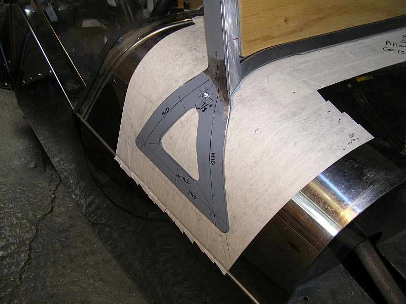
The TWO bends that are made in these flat brackets are nearer the top of the trangle, so if there is any angle change between the leading edge and the base it is quite small. It is a pity that you have flattened the old brackets, as you could have used these to compare the bends that you will make in the new ones. I have recently had to do this on an Exmo, where in the virgin scuttle there are no pre-drilled mounting holes. Advice above about the distance from screen top means that you would need to mount the screen to check, which is going to be cumbersome unless you have a second pair of helping hands. In the end I cut out a piece of cheap low density plywood (about 15mm) in the shape of the framed screen and screwed in some triangular wedge pieces so that it would stand at the correct angle for the brackets, on the scuttle top. It only took an hour. This then was put in the desired position and as i made the TWO bends in each. Notice TWO bends, the one that follows the curve in the scuttle is made by hammering gradually forming a shape with regular checks aginst the scuttle. The second is made by twisting the support coumn in a vice. It's all on the build video (at least for the Exmo) and you have to be patient and not try to do all the bending at once.
-
S7 builders will soon answer your question I am sure. In the meantime, on the Exmo where the lamp is into an almost box section, there is access from directly below. If you also have access from below the you can use a "basin wrench".
-
I have a digital copy (pdf) of the Haynes manual. I am wary about distributing it to anyone because of copyright laws. However, I have tracked down an enthusiast's site in Finland, where the Sierra was sold as a Taunus (I think).... anyway below is a link to two pdf files on the web site, both in English, one is the Sierra Service and repair manual and the other the type 9 gearbox manual. I just tried them a moment ago, they work for me. Hope this helps. https://musse67.mbnet.fi/Taunus/Korjausoppaat
-
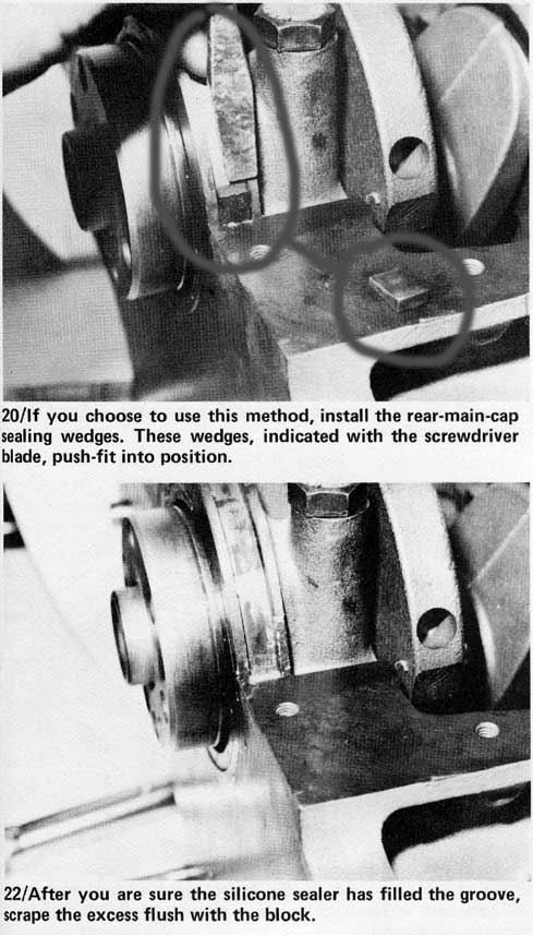
Looking at the contents list in the kit these white bits are "Rear main cap chocks" I use this as a Google search and among the hits I see two useful images:-
-
Kieran, I think that you might be slightly hi-jacking this thread although I am no afficianado of the protocols here. It might be better to start a seperate thread for this discussion. Have you made use of the search facilities here ? I did just now, I made a search for three words and selected the search option to have ALL words present the words were Exmo front strut. The search turned up 32 hits, and one of them seems to discuss your question in some detail. https://www.rhocar.org/index.php?/forums/topic/27038-exmo-suspension/page/3/&tab=comments#comment-323081 Good luck, I am part way through a similar exercise, although my front shocks are still ok, I am keen to hear how you get on in case I need replacements in future. Oh yes there is also the problem with the strut top mounts at the front breaking through the SS ... more fun.
-
P.S. I just measured the resistance across the unit, between the two black leads and its Zero, and between either black lead and the mounting bracket its infinite. So it is not a ballast resistor. The 73 ohms must be in series with the condensor, so I might add a resistor in the repacement. P.P.S. There is one on sale on eBay. https://www.ebay.co.uk/itm/Sierra-RS-Cosworth-ignition-coil-resistor/224393688484?epid=28003500454&hash=item343ee7f5a4:g:bscAAOSwAQJgPUJc OR. I think that this new BOSCH part should do but will need a small mod to the connector to wire it in. https://www.onlinecarparts.co.uk/bosch-7428717.html
-
I have the same potential challenge, the leads to/from the coil supressor are in a bad state. I have done a bit of research on this subject. There are two conflated things in some of the previous posts here. The two things are (1) a Ballast Resistor and (2) a Supressor. There is a nice piece of explanation on the Burton site that covers (1). https://www.burtonpower.com/tuning-guides/tuning-guide-pages/ignition-systems.html Reading this I do not believe the unit in your picture is a Ballast Resistor because the ignition on my Sierra is ESCII, i.e has no points. In any case this can be verified by measuring the voltage at the feed (positive input) of the coil, as explained by Burton. This then leaves the option (2) it's most probably a suppressor. What's that? I here you ask. Notice the markings on the unit, it has a marking for capacitance in Micro Farads (2.2 I believe and a resistance of 73 ohms). When the coil is producing high voltage ignition sparks some of the high voltage can get generated in the coil input circuit. Normally this should only be 12 volts. So the capacitator absorbs sudden spikes in voltage and effectively shorts them to earth without affecting the steady 12 volts in the lead. This protects any voltage sensitive devices connected elswhere on the loom, like the ESCII unit, the Rev Counter, a radio perhaps, etc etc. My intention is to verify that I do not have a ballast system and then replace the unit with an automative capacitator (frequently called a "Condensor") of 2.2 micro farads. This will be connected to the chassis by its case and be wired to the input terminal(+) of the coil. Sorry to bore you with this, I was sort of thinking it through as I typed.
-
Might be useful to know when it last run ok, was it idle for a while and now won't start or was it running fine yesterday ?
-
Do you mean the Ice Warning Sender? If so then I dont have it connected. In fact I have removed all the wiring that is related solely to the Graphic Display and Trip Computer. On my loom there are two temperature sensors, one is bolted into the engine block for the temperature gauge on the instrument cluster, the other is on the inlet manifold and is for the temp inputs to the ECU.
-
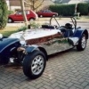
Why is the headrest at an angle ? do you drive with your head slanting ? or perhaps so tall that you twist your head to the left to keep out of the wind?
-
I agree, crude but functional, I should have said. I forgot about the plastic sleeves, they are in the small pile stuff I removed when I dissasembled the mechanism, phew!.
-
I have a fuel sender on the table in front of me. The Ohms between the pins (numbered as above) and the earth post are as follows:- Pin1 float at top (full) = 21 Pin1 float at bottom (empty) = 176 Pin2 top = 200 Pin2 bottom = 67 Pin3 top = 183 Pin 3 bottom = 183 These "top" and "bottom" positions are with the float moved by hand and obviously out of the tank, and without the plug from the loom connected. Also the sender is an old one from the 1986 donor so the rheostat will have worn somewhat, never the less the values match niduncan's, more or less.
-
Thanks, yes the BMC wipers are very different and probably a better setup both for fitting and weather proofing, however like they say on Mastermaind "I have started so I will finish" with the Sierra wipers. The pictures just above are great. I notice that there is only just enough of the spindle shaft protruding. With the arm installed, the leading edge of the nut cover dips a tiny bit under the scuttle. Weather seal is very simple (although, forgive me for this) a bit crude, I assume the Sikaflex was allowed to cure and then when the wipers were next turned on the spindles broke free. OR - did you coat the spindles with grease before putting in the Sikaflex ? so that it never adhered to them and formed a nice neat fit. I also notice that the arms are parked nicely.
-
Hey! thank you all for so many suggestions, the video link is for a 2B? not an Exmo, I have the video for the Exmo, it covers all the same stuff about windscreen construction and modifying the Sierra wipers etc, but sadly nothing about mounting under the scuttle, the kit should have come with a tube of "Deep Heat" to aleviate the back pain. I like the suggestion of taking even more material from the top edge of the brackets, I was afraid to cut into the alloy of the spindle mounts (the big round bits on the mushroom shaped part in the photo) however I do now have a spare modified motor and arms (Thanks to a freebie from G. Cash). Indeed doing that would mean being able to increase the angle of the spindles while moving the motor forward slightly ...... yes that might give the few millimetres need. I will try that. As far of the rest of it is concerned I have found that Landrover Defender arms look like they are going to fit on the spindles, and cut down blades. I have not permanently fixed the overlaps in the wiper mechanism because these will need to be adjusted to get the sweep of the blades correct. So thank you all for the suggestions, I now have a more positive outlook about this part of the construction.
-
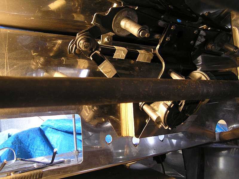
Not sure what gearboxes you are referring to. I have a motor with a crank and attached rods that drive the spindles See picture below. You can see that I have even cut down the area around the spindle bracket and that it is butting hard against the under surface of the scuttle. I am no spring chicken, and bending over to work in this area is killing my back. I envy the owners of models where the scuttle is not fixed like the Exmo, groan groan moan.