Sparepart
 RHOCaR Member
-
Posts
351 -
Joined
-
Last visited
-
Days Won
14
Content Type
Profiles
Forums
Events
Store
Community Map
Everything posted by Sparepart
-
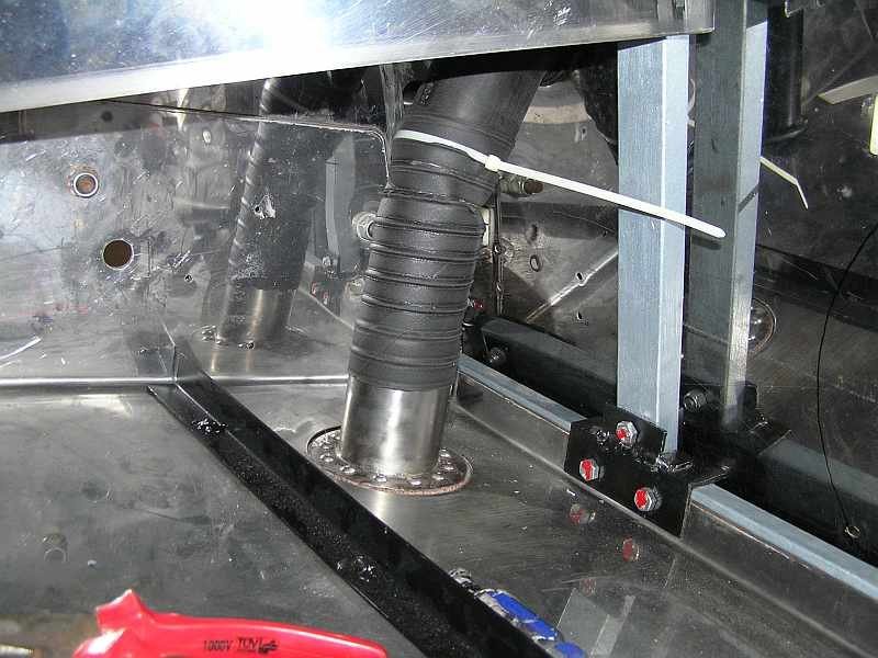
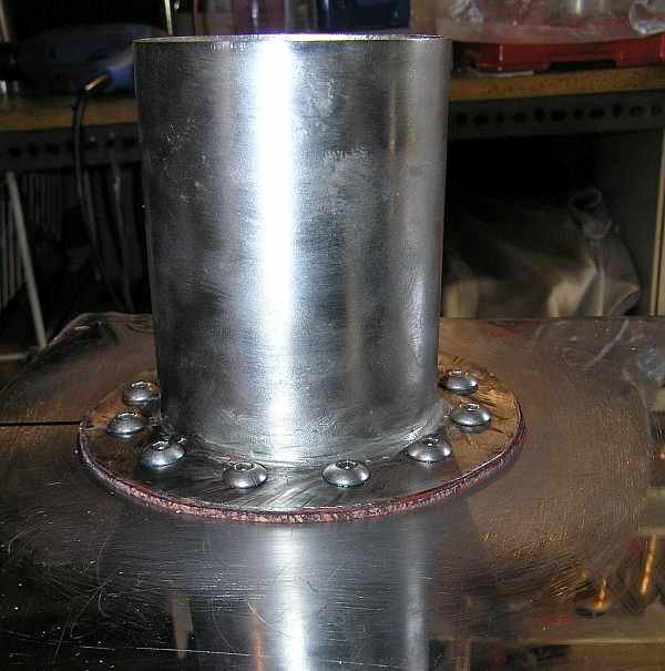
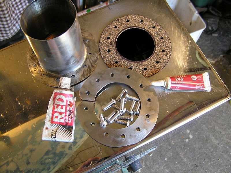
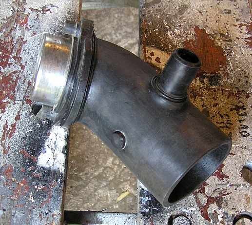
I also had petrol fumes at the rear using the RHE supplied "box" type tank with the Sierra filler pipe rammed through the hole in the tank using the Sierra rubber grommet. As you say a new grommet is expensive, and didn't work too well. Now I am rebuilding the car, and have made a large bore filler flanged SS pipe to bolt onto the tank, and cut back the plastic Sierra filler pipe below the breather to allow for a flexible connection to the new pipe on the tank. I attach some photos of what I am hoping will fix the problem. There is an inner ring with a slot that has nuts welded to the lower face (not visible in snap) this was carefully manoevered into the tank and the flanged pipe sealed and bolted down with a cork gasket as shown. So there is no attempt to weld anything on the thin SS of the tank, all the welding is the flange to the pipe, which I did with MIG (should really be TIG) but I have tested its "Petrol tightness" by bolting it to a flat plate and filling the pipe with petrol and checking for any signs of seepage, left overnight without problem. I am also hoping that this will cure the other problem I had, that of having to fill the tank very slowly lest petrol climbing in the filler neck shut off the fuel pump at the filling station.

-
Just FYI, the Exmo build instructions used the same mounting hole and bush as used on the Sierra, the one that has a the bolt head that is scraping, as on your car. This means that the subframe is not rigidly fixed to the bodyshell, there can be some movement via the rubber in the bush, probably good for absorbing vibrations etc. Not long after I had mounted the subframe as per these instructions I received a build update from RHE telling me that some cars had failed SVA due to this small possible movement and safety concerns about bush failure leading to the subframe coming adrift. The new instruction was to bolt the subframe directly to the big steel plates using M12 high tensile bolts, on on each side. This involved opening a hole in the lower part of the subframe large enough to get a socket wrench head to the underside of the subframe plate through which the bolt protruded. The message to use a really tight nylock nut here and check it pre MOT every year was repeated several times. Consequently the bolt through the original Sierra bush became redundant.
-
You have fixed it, and I am still puzzling about what was scraping what ?, was something coming into contact with the road ? I am just curious.
-
Possibly a frivolous comment, but perhaps there is no air getting into the petrol tank, so after a while the pump is not able to extract any liquid petrol. I would have thought that if the tank is sealed, at some point the partial pressure would mean that when the pump sucks, the petrol starts to vapourise and either the pump pumps vapour or the petrol just moves back and fore in the pipe. I suppose you would hear a hiss when taking the filler cap off, if this were the case.
-
The pickup pipe in the tank has filter on the end. Could be a layer of crap in the bottom of the tank made up of reatively heavy bits, when the pump sucks the petrol up the bits are gradually picked up on the outside of the filter mesh until no more petrol flows. Then, left idle, the bits drop off under their own weight. You could run the engine until it stops and then as quick as you can pull out the gauge/pickup pipe to examine the filter.
-
In the original Sierra systems the pulsed input feed needed by the tachometer is a green wire that connects to the low tension (12v) connector on the coil. On the coil, apart from the thick HT lead going to the distrubutor, there should be a single (normally black) wire that comes from the ignition switch. The other connector would have two wires connected (normally green), one of which goes to whatever ECU you are using, and the other to the tachometer. When the ignition is on the the green wires should be live. The tachometer will have 3 connectors, one to earth, one to a constant 12v (with the ignition on), one with the pulsed feed from the ignition coil (probably green). So you need to get out a volt meter and check the wires that have not been connected, or visually look for the one from the ignition coil (probably green) that is probably not connected to the tachometer.
-
This is just a suggestion, I've not tried this, however have you considered fitting a smaller ball. That is chop off the current one thats too large, drill a hole and fit a smaller ball to match the Ford cable that you have. Various sized balls are available, they are used by RC model builders for example see the links below. https://www.ebay.co.uk/itm/154109713879 https://www.ebay.co.uk/itm/284753072675
-
Okay,Okay, I was a bit lisdexic with the numerals, I am a dislexic, agnostic, insomniac, I lie awake at night doubting the existence of dog.
-
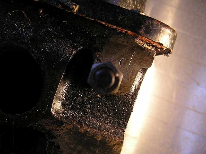
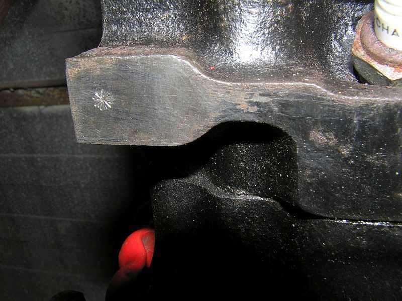
I am exhuming this old thread because I have a very similar question I'd like to share. I have a 2.0 L Pinto, from a 1968 Sierra, I'd always thought it was a leaded head and have been using additives. Now I have it out of the car ready for reconditioning, I thought I'd check it for what is stamped on the head. As per advice in this thread I looked at the flat face next to number four spark plug, and saw a sort of asterisk stamped, so assumed a leaded head. However on cleaning up a similar face near number 4 exhaust port I see a letter stamped, which with the head in its normal orientation looks like an odd shaped "d", Turning the photo I took upside down, the letter looks more like a P. I have searched in loads of forums for use of a letter "d" in a pinto head to no avail. So I am now assuming that this head might be an unleaded head with the letter "P" stamped upside down near number 4 exhaust port. What do other members think ? ... photos attached.
-
£325 is the correct amount at the moment, see:- https://www.gov.uk/vehicle-tax-rate-tables/rates-for-cars-and-light-goods-vehicles-registered-before-1-march-2001
-
 Well, ... to be PEDANTIC, the early kits used a Mini bodyshell for the passenger compartment. You indicate that both were built after 2000, so it's obviously unlikely that one used an old (ca. 1985) kit. However, if such a "Mini" kit had been used, then it might have retained the original Mini number as a "radically modified vehicle". For info, my car is like the A reg Beauford, built in 2000 yet having a C reg number like the donor vehicle.
 -
Assuming that your engine is not running and you have a brake servo then the hiss is possibly the diaphragm in the servo forcing air somewhere like back to the inlet manifold. Disconnect the vacuum pipe and listen if the hiss changes or disappears. If this is the case then it can be ignored from the point of view of bleeding the brakes.
-
I have the same behaviour on an Exmo, obviously no use to you to know this, however in the days of SVA it wasn't an issue, the tester made no comment about having to unwind the steering to straighten out from a turn. I now know that most of the problem was related to the really poor bearing set up on top of the strut, causing lots of friction. As mentioned above by agent_z anything you can do to push the bottom wishbone forward and the top one back is going to help. If you have bushes that are pressed into the wishbones then perhaps you can press them off center to get some adjustment. Also I suppose that a lowering of the back of the car would have some effect on the angle of castor at the front, do you have any rear ride height adjustment, or raise the front as well. Oh yes, something else I found was at the universal joint where the column is connected ot the rack. When the weight was off the front wheels I could easily move from lock to lock just by pushing/pulling on the wheels. However when the car was back on the ground, the pressure on that UJ means that the small amount of play in it caused the top of the lock nut to slightly foul on a bit of poor casting on the yoke. Just a few strokes of a file to remove the casting mark and the steering was much free-er.
-
Out of interest I have done a bit of Googling, I found records of 3 RS Daytona Spyders, SAN 948S is the car that features earlier in this post, currently it is on SORN, so not on the road. 978 DJU is taxed so most likely on the road. There was also one in Holland NV-82_ST. One came up for sale on e-Bay as an unfinished project, this was a while ago, however the seller appears to be still active, they have a comment from a customer in the last six months. The seller's handle is "daytonalovercars", I attach a pdf of the ebay page showing this seller, so she/he can be contacted via ebay, and might know what happened to the kit. daytonalovercars-on-ebay.pdf
-
An early MGB roadster, bought as a project, everything I did to make it good brought more grief. Me towing it home with dad piloting it, he started the engine, to get heat from the heater, who knows what happened, but the next time I ran it, the big end bearings were grumbling and the oil pressure low. Replacing the bearings from below, engine in situ, sump off, one of the pistons dropped past the rings in the bore. Rear weel arches were replaced, this was expected, what was not was that going over a sleeping policeman both rear shock absorbers, the type with an arm, twisted up the chassis mounting point rather that move the arm, leaving them hanging in the air and the car bouncing down the road. Even though I had the clutch replaced, a little while later the slave cylinder rubbers burst and deposited all the fluid under the car leaving me stranded. Then as you might expect the main bearings started to rumble. The Twin SUs were never in balance for more than a week. There's lots more. Eventually I was surprised that a garage took it in part exchange for a Mk1 Ford Capri, what a relief.
-
I learned to drive in a sit up and beg Ford 8 (1172cc sidevalve), then upgraded to a Mk1 ford Zephyr 6 cyl a bit over 2 litres with bench seat and 3 speed column gearchange, no synchro into 1st, but you didn't need that gear much, then a Ford Anglia 105E with a larger engine 1340 cc from a Classic.... I'll stop there.
-
Just a thought. Before you press the brake pedal, check the gap between the back of the pad and the piston and the pad and the disk, see if the pads are quite free. Do your pedal pumping thing until the brakes are firm, now the pads should be firmly gripping the disk. Then release the brake pedal. Now there should be a residual pressure in the pipe that keeps the pads very close to the disk, actually very slightly still braking. If the pads/pistons retire away from the disk then this could explain your first ineffectual pump. You might find no real difference in the piston/pad freedom in which case it would rule out a lack of "residual pressure" being your problem.
-
You have not indicated the carb type or ignition system, if you have the carb that goes with the ESC II ignition module as fitted to some Sierras then you will have a "Power Hold" relay, which keeps the ECU powered up after the ignition is switched off. In the manual it indicates that this lets the ECU return to an idle state and reset the stepper motor on the choke and reduce likelyhood of "overrun" by venting the inlet manifold. So if you have this sort of system then a malfunction of the power hold feature could cause your symptoms. On another tack, if there is a "hotspot" its not likely to affect more than one cylinder, so you might try running the engine on three cylinders and changing the non firing cylinder to see if the there is s difference when you turn off the engine. This is just a suggestion, Ive never tried, perhaps running on three is too rough to notice a difference.
-
The 1.6 emax is more properly designated as Pinto variant TL16E, the fordopedia parts catalogue lists the timing belt as have 122 teeth Ford part number 6139911. Use "Ford 6139911" in a Google search and discover several sources for this belt for example: https://www.123spareparts.co.uk/oem-number/6139911 some also include the tensioner etc which you will aslo probably need. https://www.fordopedia.org/parts-catalog/finis/6139911 Hope this helps.
-
The problem with the metal shed is that during spells of cold weather the thermal conductivity of the metal means it gets really cold. Then, usually in this country the cold weather is followed by mild weather with high humidity, the water then condenses out on the metal surface until the metal warms up, after a frost it can sometimes fall like rain on anything in the shed, you think that there is a hole in the roof, because in some places the water dribbles down an edge and build pools of water. Wood gets just as cold and no doubt condensation forms, however as long as its not painted with water repellent paint, the humidity is absorbed into the wood.
-
I have done a bit of Googling (I guess thats a verb now) I think that you will find there are two ford OEM numbers, one for the head gasket alone and the other for a head kit that includes the head gasket. Search with "Ford 5028468" for the kit and "Ford 6905862" for just the gasket. A description of the bore of the engine is already in the following thread https://www.rhocar.org/index.php?/forums/topic/44486-e-max-engine/ where it is quoted as 81mm, the gaskets that the OEM numbers search turns up are 83 mm .... does the head gasket need a 1mm gap ? not sure, if so, then these look right. Here is a link that turns up if the OEM is used in a Google search. https://www.onlinecarparts.co.uk/oenumber/6905862.html Check it out.
-
Please have a look at the following link, I am not sure if it will help or further confuse, according to this parts catalogue there are an assortment of sizes depending on position and year of manufacture. All the sizes are bigger than your measurement, like 38 and 48 mm. https://www.fordopedia.org/parts-catalog/pinto-ohc/B1.40
-
-
I'm not 100% sure about this, but on my car the carb is the other way round, with the throttle cable coming to the rear of the inlet manifold. The picture with the red cam cover shows this, but the first picture looks like a view from the front of the car, and the throttle shaft pointing forwards, which not the right way round. This doesn't answer you question about how the linkage works, but if it is the wrong way round the cable may not reach or have the correct approach to the mechanism.
-
Perhaps the extra 0.5 mm radius of the piston has increased the volume (pi r squared h) of the stroke so that now the standard compression ratio is when the piston top is a little lower ?. How about trying to measure the CR ?, seal the valves in one of the cylinders with thin layer of silicone sealant and have the spark plug in, and with the head level, flll the chamber with water and measure exactly the volume of water used. Add to this volume, the thickness of a gasket and the gap above your piston (pi r squared the distances) and you have the volume of the combustion chamber. Then measure the stroke to calculate the induction volume. You will then have the two volumes to work out the CR. Costs nothing to try, and then with luck you will know from where you are starting in your quest for high compression. I'd have thought that you could make an accurate liquid measurement if you can use a medical syringe to empty the liquid as they should have accurate volume markings and also perhaps a liquid with low surface tension, like say paraffin, so that you can fill level without that bulge on the edges that water produces, or maybe water with detergent or dishwasher clear glass liquid.