Sparepart
 RHOCaR Member
-
Posts
351 -
Joined
-
Last visited
-
Days Won
14
Content Type
Profiles
Forums
Events
Store
Community Map
Everything posted by Sparepart
-
Oh, yes, in the small print above the box on the inspection form, it says "Design Weights", I should have gone to Specsavers..... in fact I now have an apointment for the 6th... so sorry, I don't know how much the car weighs after all.
-
At the time of SVA my EXMO weights were front axle = 519KG rear axle 519KG thats with spare wheel, fullish tank and myself in the car, yes, exactly the same weights front and back, thats why I remember. So total = 1038KG a bit heavy I guess, perhaps too many Pizzas before the test?
-
You might want to consider purchasing a steering column with the switch and barrel etc. For exampe: https://www.ebay.co.uk/itm/Used-Genuine-Ford-Sierra-Mk2-steering-column-barrel-and-key-/373650618339 Cost £50 .... too expensive ?
-
There is part of a previous thread that might help regarding the method that uses fishing line, look at this:- https://www.rhocar.org/index.php?/forums/topic/49253-another-exmo-/page/5/
-
Knocking sound on refurbished (only 20 miles) pinto engine.
Sparepart replied to Kevxathome@gmail.com's topic in Engine
A million years ago when I was a poor student I ran a Ford Anglia on a series of 109E engines from a scrap yard, only a three bearing crank, very very worn, but the big end knock was more of a grumbling sound rather that what sounds like a "clattering" in this case ..... anyway ....in all cases the oil pressure warning light would flicker on/off when idling and hot. What is happening with the oil pressure warning light in this case ?? -
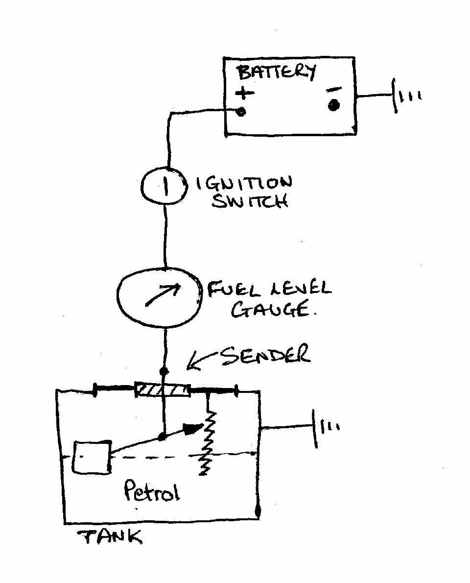
At great expense, I have comissioned a technical drawing of the basic way a fuel gauge is wired up. The principles might help you figure out which wires you need to connect to what in your case.

-
I agree. I looked at the Kitspares product that you probably have. https://kitspares.co.uk/collections/fuel-system/products/fuel-sender-unit It does not match the drawing above because it is probably for a really basic Sierra maodel, maybe the pickup. The sender with the three pins is more complicated because as well as the variable resistance for the fuel gauge it can also be linked up to two other features of higher spec Sierras, that is, the trip computer and the low fuel level warning lamp. So for most folk with a kit car only one of the three connectors on the sender unit is used. Essentially that is what you have, a sender unit that has the single needed connector.
-
There is a previous thread that discusses the resistance values at the pins of a working sender. https://www.rhocar.org/index.php?/forums/topic/49494-sender-unit Unfortunatey niducan's photos no longer seem to be accessible, note one pin goes up in resistance, one down and the other stays constant, so it is possible to wire the conections up so that a full tank might read empty and vice versa, I think.
-
Am I correct in supposing that the windscreen is removed before taking it for an MOT ? then replaced after ?
-
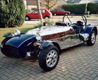
Wow! what a car, surrounded by the bits and pieces of my rebuilding, looking at all the work still to do, I heard a whisper saying, "Throw this load of tat away and buy that car!". At least, as I continue, I can see what is possible, eventually, perhaps, sometime, maybe.
-
I notice that you are a recently joined member, so i feel I have to mention that unless you are replacing an existing hood, and hence have an accurate pattern, there is going to be a fitting exercise involved. This is because during construction the windscreen position was determined by the builder, there were no pre-drilled holes for the pillar mounts in the factory bodyshell. This also applies to any frame or studs that were fitted. That is to say eatch hood will be unique, starting from a hood of generally correct proportions. You also did not mention sidescreens etc ... do you have some already ? I apologise if you are already on top of this stuff, I know that it does not help to get a response that does not suggest a solution, only raises more questions. Although not urgent, I too am on the lookout for a hood, frame, sidescreens etc for an EXMO so will be keeping an eye on this thread.
-
Ah, I was wondering how it might work, floatation seemed unlikely, I thought perhaps a change in capacity between two plates, but a rise in temp is a good possibility. I threw away the "Auxiliary Warning Module" to which the sender should be connected a long long time ago. I'll check the resistance, if its a heating element there should be a lowish resitance, maybe like 10 ohms. Perhaps then I can gently heat it from outside, wave a flame at it, and see if it goes open circuit. In any event if I do want to use it again, with no Auxiliary Warning Module, I would need to design a circuit to power it correctly and illuminate a lamp when the circuite opens .... mmmm... probably leave that to a winter project.
-
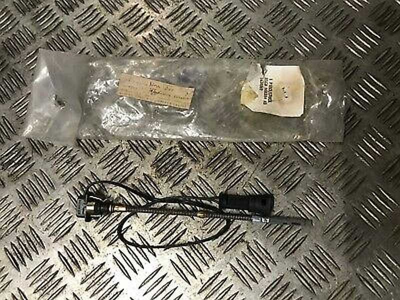
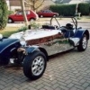
Her is a photo of one thats for sale on the web.
-
The hole in the block is about 1/2" diameter on the offside near the mounting arm but right down just above where the sump starts. The sensor is then quite long about 6 inches roughly, a long thin metal probe with a wide "bung" at the top where the sensor wire exits to a connector. When the "bung" is in the hole the end of the sensor is then down in the sump at a similar depth to the end of the dipstick.
-
During the original (rushed) build I removed the sensor for low engine oil level from the block and tapped a wooden round peg in the round hole. Now, during a rebuild I have more time to consider... should I properly seal the hole, which kept weeping oil .. or reinstate the oil level warning sensor. To be honest I am thinking that it is not needed and just one more thing to leak or go wrong and I am not sure if it is just a single point sensor or a gradual sensor. So before I throw it away I was wondering if anyone else has fitted/used this sensor and has some experience to share.
-
Multiple questions, does a body kit make it a kit car??
Sparepart replied to FinkPloyd's topic in Fitting & bodywork
To reply to your original first question number 5 (yes you have two question no 5s), You want to know how much of the car has to be non standard before various tests are required. This is all explained at the .gov website, look down the list of degrees of modifications, from rebuilt vehicles to radically altered vehicles and see whats needed to get them on the road. Not all need a type approval test. https://www.gov.uk/vehicle-registration -
On the similarly bodied Exmo I have used the small "microbore" copper pipe (6mm I think probably what you have there). Like Harry it is routed up into the "boot" and the out through the nearside wheel arch to run in the box section under the passenger's arm and to the fuel pump. You can create a "flare" by soldering an olive at each end so that the rubber connectors can be pushed over and a clip put behind the olive. In that long run down the side, I placed a plastic (PVC?) 15mm water pipe. The cooper pipe runs through this to protect it from any sharp bits of SS that have not noticed or can't get to. Long time ago. Only an SVA for me, all the checked on was that it was secured at regular intervals, they dis not measure, just a visual assessment.
-
I think richyb66 means that the alternator is earthed through the mounting bracket, so it has to be firmly mounted for the belt to drive it, hence should be a good earth otherwise it would fall off. This assumes though that the engine block is earthed. I think that the alternator should give pretty much a constant output voltage which is controlled by the regulator circuitry inside the alternator. The regulator varies the field coil current to keep the output voltage constant. When there is demand for current from a flat battery, or a battery just a bit low after starting, or from light bulb filaments, or cigar lighter socket etc this manifests itself in a drop in resistance at the ouput from the alternator and from school I remember V=IR, so to keep V constant with falling R the I has to get bigger, so the regulator increases the magnetic field coil current in the alternator to generate a bigger current output and the voltage constant. With a bigger magnetic field the alternator gets harder to turn and puts more load on the engine via the dtive belt. So possible drops in voltage could also be caused by a loose drive belt, although you normally hear this squeeling from cold. The regulator is the most likely source of the problem. What happens to the voltage if you turn on the headlights or any other current consuming device ?.
-
I agree, I have just put mine back together on the bench, outside the car. As the boss is tightened down more thread appears at the nut (obviously), and the spring at the bottom gets compressed as more of the shaft is drwan into the tube. The two thrust washers slide on the shaft, the top one is pushed down by the cam and the bottom one pushed by the top of the spring. When the boss has reached it's final position, firmly pressed down on the taper there is still plenty of compression available at the spring. So the cam is not crushed it only has the spring tension pressing on it. I lifted up the assembled unit and put the bottom end of the shaft on the floor, grasping it by the outer tube (the part that is bolted to the cross member under the scuttle) I can push the outer tube down the shaft against the spring and then it moves back when I stop pushing. There must be a reason for it to be like this, possibly to absorb small compressions that try to push the shaft towards the driver ? reducing/eliminating vibrations ?.
-
Now I need to look at my column more closely, because my cam is broken, I think that when I put the Mountney boss on the shaft I probably failed to notice the notch that molded into it, so did not put the notch just above the cam, damn!
-
This is an odd co-incidence, I am just rebuilding the steering column assembly on my Exmo. When I took it all apart I noticed that the indicator cancellation cam is broken. On closer inspection it seems to me that this cam also acts as a spacer between the bottom of the boss and the top of the small ball race thats at the top of the sterring column tube. You could check the state of your cam ?
-
A bit more seriously though, would I be wrong in thinking that if either diode fails and becomes "short" rather than open circuit, then both coilpacks could discharge at the same time ? so you might want to consider the long term reliability of this solution.?
-
Ah yes! all solved by a bleeding resistor,
-
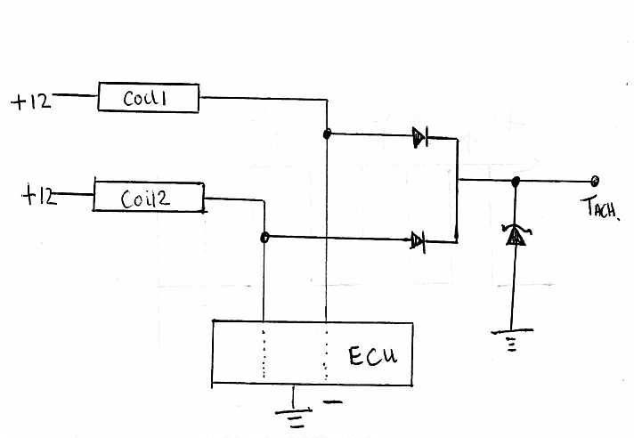
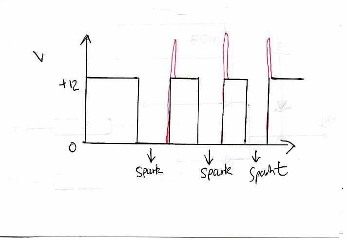
I am no electronics expert.... so I leave others to correct what is about to follow. From your diagram I am assuming that you have two coil packs and therefore a "lost spark" system. That is why the circuit is combining the negative sides of both the primary coils. I have spared no expense in making a rough drawing of a suggestion for a slightly different circuit. A spark is generated by the secondary coil (High Tension Coil) when the voltage at the primary coil collapses from 12v to 0. This collapse causes the magnetic energy stored in the core of the coils to collapse and the resultant "flux" is what gives the high voltage in the many turns of the secondary coil and thus a spark. In old fasioned engines its the points that disconnect to cause the collapse, in electronic systems the collapse is controlled very accurately by the ECU. Essentially the ECU decides when and how long to connect the "negative" side of the primary coil to earth (or zero volts). A crude graph of voltage at the -ve side of a primary coil against time is thus. When the ECU stops earthing the -ve side of the primary coil it suddenly rushes up to 12 volts again, however, in all this excitement the high flux in the core causes the voltage to "overshoot" and return to 12v in a voltage spike, displayed in red above. I am going through all this to get a clear picture in my head about what the elements of the suggested circuit are doing. Firstly the two normal diodes are essential because they prevent the earthing of one coil by the ECU from earthing the other coil and causing an unwanted spark. The Zener diode is connected to earth so that any voltage higher than the breakdown voltage (in the case of your zener I think it's 13.5v nominal) is discharged to earth rather than blowing up the Tacho. Now there might be other elements needed like resistors and such like (I am NOT an expert) but I hope this suggestion might help.
-
Unfortunately the DVLA website is quite clear on what is needed to change the V5 either engine number or capacity. Change of engine number or cylinder capacity (cc) You need to provide either: . a receipt for the replacement engine . written evidence from the manufacturer . an inspection report provided for insurance purposes . written confirmation on headed paper from a garage (if the change took place before you bought the vehicle) https://www.gov.uk/change-vehicle-details-registration-certificate/what-evidence-to-give When you bought the crated motor, did you not have a receipt ? or a guarantee ? if so surely the engine would have been refered to using some sort of serial number .... just in case you were not happy with it and wanted to return it, the seller would have wanted to make sure you were returning the same engine that had been supplied..... ?