Sparepart
 RHOCaR Member
-
Posts
351 -
Joined
-
Last visited
-
Days Won
14
Content Type
Profiles
Forums
Events
Store
Community Map
Everything posted by Sparepart
-
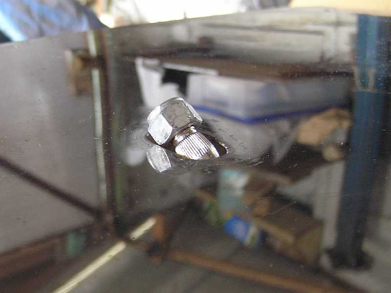
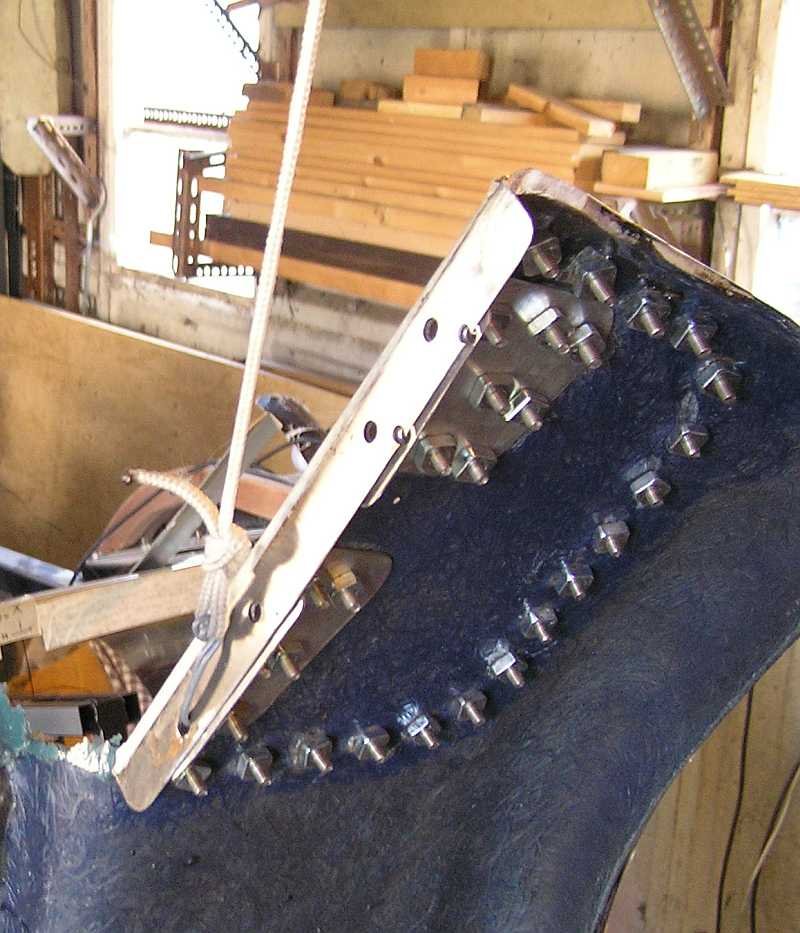
I am fitting a windscreen, wipers, demister, washer etc to an Exmo for the first time, having left them out previously to avoid test issues. I have modified the Sierra wipers as described in the build video. I have constructed bracketry on the firewall to mount the wiper mechanism in a position that gives the most possible penetration of the spindles through the scuttle. The mounting does not require any support from the scuttle itself. The spindles are protruding through the plasma cut orifices made by RHE. I attach a photo of one of these with a nut attached. As it stands, there is not enough clearance to attach a wiper arm. I have therefore a dilemma. I have invested a lot of time in this so would like to get it to work, rather than binning it and starting again with BMC type wipers. I could enlarge the hole to fit the arm, but the arm needs to move back and fore so I could end up with a big hole. Another option would be to extend the spindle with a threaded collar and lock it with cross drilled pin, but the spindle is brass, would this weaken it too much?. AND there is the challenge of weather sealing ....... So has anyone out there managed to dig themselves out of a similar hole ?

-
Old chestnut: Lady asks a Scotsman, "What's worn underneath your Kilt?" He replies "Nothing madam, it's all in perfect working order!"
-
Dave, I have PM'd you with an offer.
-
Dave, I am interested in this. some questions. How do I/you know it is unleaded ? What's the history ? i.e. Was it on an engine that you scrapped or something ? Was it working ok before it was removed ? I live too far away, given current restrictions, however I have a sister living in Shrivenham, would you consider delivery to her for a modest recompense. ?
-
I am fortunate to have a copy of the Haynes FORD SIERRA Service and Repair Manual 1982 to 1993 4cyl Petrol. The wiring diagrams are not easy to use as all the major components have numbers on the diagrams, so you have to go back and for between several pages in order to see whats what. On page 13-54 (Diagram 1) the "Speed sensor" item number 150 shows a yellow/brown wire going to Diagram 4a (square H8). If I turn to Diagram 4a, I see this yellow/brown wire going to pin 4 of item 58 (which turns out to be EEC IV Module) .... So in answer to your question, it appears that the speed sensor input is required by the EEC. I do not have this engine or EEC (I have SOHC carb) however on mine the speed sensor is a detachable part of the speedo cable which is driven from a mechanical output on the Type 9 gearbox. It was also used by the "Fuel Computer" on up market versions of the Sierra equiped with a Graphical Display.
-
Yes, thats about right. I have extracted the instructions from the build video for you to see what was the "offical" way to do this. There are two clips, one short and another longer (parts 1 and 2 resp ), this is because they spanned two of the tapes that I had. The quality is poor, but turn up the sound and have a look. You will see that you do not appear to have big enough stone guards to form a lip to bolt the bottom of the wing to the tub..... so you will need to get hold of original sized ones somehow ? ... anyway here is a link to the two clips on my cloud space. Have a look.... you might decide not to go ahead with this after you see what the designer does. https://btcloud.bt.com/web/app/share/invite/n5IgsfjkFB You notice he refers to (but does not show) a rightangled piece of steel that fits inside the wing at the join with the tub, and says to drill four holes to bolt it on etc. This is what I have done, using countersunk small ss bolts, the heads of which are then covered by the stone guard when that is fitted. So you too could do that, as your guard looks big enough to cover holes near the join with the tub. As for cutting the glass, well I just have Gel coat, no paint, and used a piece of fine hacksaw blade fitted with a handle. You can just wrap a load of masking tape around one end of a blade to get the same sort of thing. It worked well, as long as you don't try an "force" the blade to cut too much on each stroke, just be patient and work gradually with gentle pressure on the blade. I did NOT fit the dummy piping. Personally I think it looks naff, and anyway that bit about pop riveting the ends to the body looks dodgy, I guess you should pull them out after?
-
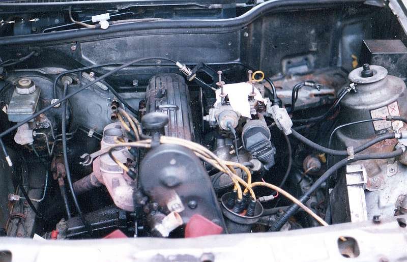
For the same reasons, mine is mounted in the engine bay, vertically just opposite the distributor. I have an EXMO so a photo is of little use to you. I have a snap of the donor engine bay (below), you can see the ESC2 mounted on the inner wing, bottom right.
-
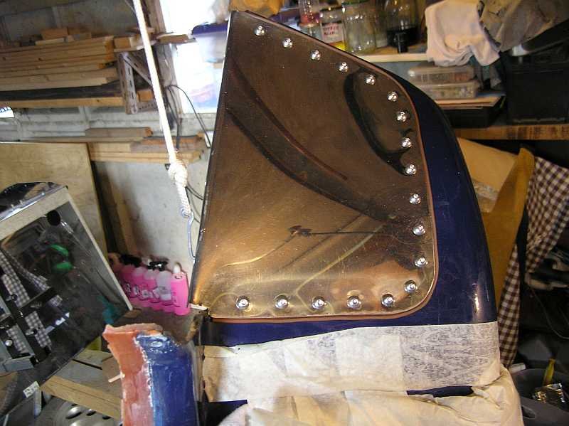
This one of many challenging parts of the Exmo build. It is covered on the VHS build tapes, I assume you have not viewed this otherwise you would be trembling even more about your paintwork. When I did my original build I cocked this up big time. Essentailly your red line is on the right lines, except the vertical line needs to be even further back so that you can eat into the area at the bottom front of the wing where it meets the side of the tub. You will have noticed that the body sort of bulges out a bit at the bottom so that it covers the end of the subframe (just). On the video, Tricky Dicky slowly hacks away at the fiberglass until he gets two things right. Firstly the right angle at the top, where the short red line is on your picture should fit on to the right angle of the top edge of the tub, where your elbow would rest. Secondly ... if you try to do this, then the buldge at the tub bottom stops you moving the right angle over to attach it, so you remove a strip from the bottom edge of the fibreglass up wards in a narrowing way, the strip cut out is wide at the bottom and gets narrow as it goes up, like a long thin pointed triangle. If you get it right then when the right angle fits snugly the edge of the fibreglass along the wing edge meets the tub edge neatly with a small gap. You now realise that there is no angled bit left on the wing to attach to the side of the tub. This is where the stone guard comes into play. The original supplied guards have a rightangle bent into the edge that goes next to the tub. (it looks like this has been cut off in your picture). When the stoneguard is riveted onto the wing this edge goes right up to the tub and is bolted to the tub, this is invisible from outside the wheel arch. Now I am going to attach some photos from my build, these might show what's done on the build video, except that what you see in my case is my recent attempts to fix the mess that I made originally. What happened when I tried this was that I took too much material from the wing, This was because I had not properly secured the rear if the wing when I started removing material, the rear had moved out a bit, like on end of a see saw, so by the time I noticed and pushed it back in, the gap I had made was huge. Then not to be beaten I tried to close the gap using clamps to pull the front edge of the wing in ..... Bang! ... I cracked the top rear of the wing ... it was not able to take the twisting. If you want I could try and extract the bit from the build video and put a digital copy on my cloud share .... since this takes a while ... I'll do it readily but only if you think you would like to take a look.
-
Have you seen the information at the link below ? It list the Engine code for the variants, the code should be stamped on the engine block. https://toyne.org.uk/zetec-engine.html
-
This is great, just the sort of detail to keep me happy for a long time. Just for the "fun" of it, I am thinking of making a crude high current ammeter by having a coil of thin wire around a thick wire through which the high current will pass. Depending on the number of turns in the coil, I would hope to generate a voltage in the 0-5 v range that I can measure using a Raspberry Pi. This might then have sufficient granularity to generate the graphs of current against time for the spikes. A sort of cheap oscilliscope. Of course this will have to wait to the next lockdown. Anyway thanks for the document link, I now plan to replace the fusible link with a fuse with some sense of competence.
-
Thank you for your reply and the calculations and advice. My focus was on the current given out by the battery, I had not considered the alternator. I have done a bit more digging around, and am 99 percent in agreement with your notes. The only aspect that I think might matter is that of how long it takes the fuse/fuse link to "blow". Here, I think that the length of the link or type of fuse has an effect. I was thinking about two rediculous extreemes. If I used a very long fuse link it would not blow, just get hot and the high resistance would severely limit the available current in normal use. If I used a tiny tiny length of fuse link, then it would be able to support the accessories, but then blow when the alternator kicks in after a start. So the puzzle is that if a fuse rated to take the maximum possible current is used then it will be too high to protect the "normal" wiring for the accessories. That's why I think that the length of the fuse link matters, it is in effect a "slow blow" type of fuse. It probably gets a bit hot when the alternator kicks in but won't blow right away, it lasts intact until the the max current peak passes. I assume that this must be a short time ?, a few seconds/ (no Idea). Anyway that is why I would like to replace my fuselink with a piece of the correct length. The wire I need is available from the USA but I don't know what length to use. If I go over to using a blade or cartridge or other sort of fuse I really aught to use a fuse that mimics the "slow blow" characteristics of the original fuse link. Perhaps I am being too pernickety about this, after all I have several spare bottles of Lucas Loom Smoke in the garage in case any should leak from the loom. :-)
-
I am stripping out all the unused wires from the Sierra loom that has been used in the Exmo. I now realise that when I fitted the loom back in 1998, in my haste to finish the build, I cut out some of the length of the fusible link wire that connects directly to the battery positive terminal. At that time I was ignorant of it's importance and just thought it looked a bit flimsy. I now see (from the bit that remains) that it has "16GA FUSE LINK" written on it. I wonder if anyone know how long it should be ? as I would like to replace it. Alternatively has anyone changed it for something like a Maxi Fuse, and knows what rating the fuse should be ?. I looked at web sites that discuss this and they seem a bit vague about drawing an exact comparison between a length of fuse link wire and a fuse rating.
-
At the risk of being patronising, are we to assume that you have carried out some basic diagnostics ? that lead you to suspect the H.I.S.S. ring. I know nothing about Honda engines (so shut up then I hear you say) ... however a bit of Googling and I found a short Youtube that takes the viewer through a series of tests to attempt to isolate starting problems with a Honda engine. It begins with a check that the battery is up to the job, for example a poor battery can not provide enough voltage to the ECU when it is under load from the starter motor, the engine cranks but does not start. Then the video checks the plugs and ecu connectors etc etc etc ... the fueling system by spraying ether into the air intakes etc etc. The link is below. The superblackbird has the two wire diagnostic mode connector mentioned, that gives fault codes. Again, I apologise if you have already carried out this sort of investigation.
-
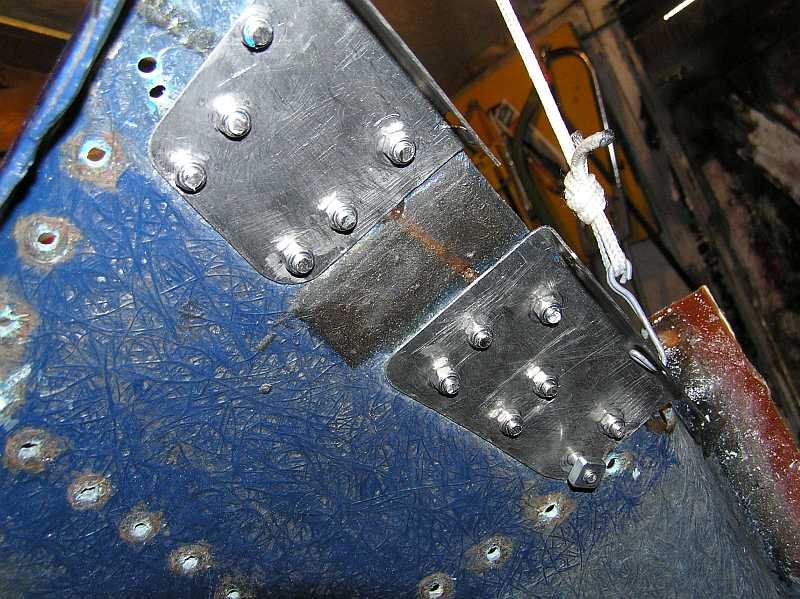
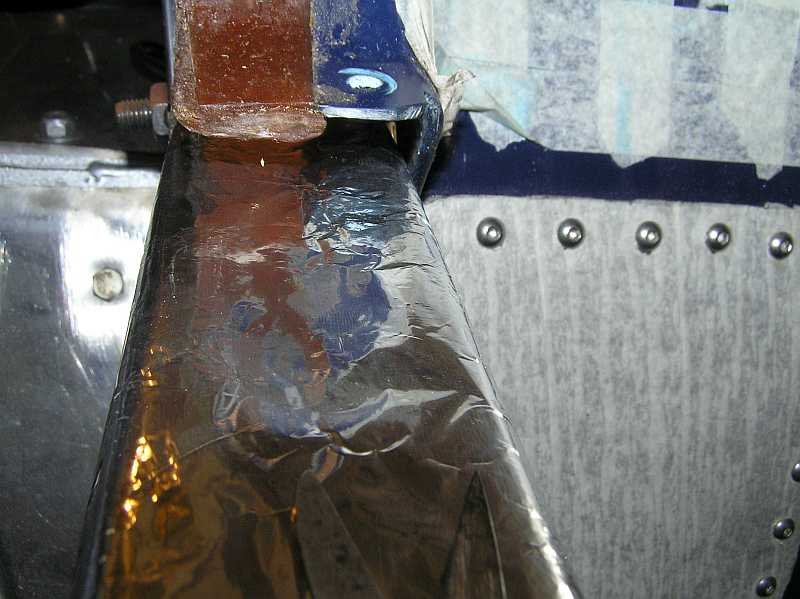
The way that the windscreen is attached to the scuttle looks unique, dissapearing through a hole. I have not seen that before on a RH.
-
Just a suggestion for something else to try, with a hot system, engine not running, in gear, handbrake off, rock the car back and fore, see if the same clunk occurs. It might help differentiate between a problem with the clutch release mechanism and some "play" in the drive train. For example, a defective spring in the clutch plate, pressure plate, worn spigot bearing, input shaft bearing.
-
Oddly enough I am right now looking at the lighting circuits as part of a rebuild. The 1986 Ghia donor had electric everything, so I am junking tons of wire. I can see that the headlights main beams (thick white wire) are not on a relay and have done 115 K miles so far through the stalk switches (two switches on/off and the dip/main switch). The dip beams (thin yellow) however ARE through a relay. I will be putting the main beams on a relay as part of the rebuild.
-
I managed to get mine punched directly to the right side of the drivers floor panel, about underneth my knee. There are challenges, one is to keep a nice straight line if that matters to you, the other is to get the punches the right way round, because when you look at the end it's like mirror writing, you need to think like a typesetter. I managed to get one of the characters wrong, a back to front B I think....... anyway no one complained at the SVA, and the MOTs have just looked at the plate that I rivitted on the bulkhead.
-
I apologise for any confusion I may have caused. I did say "Things have changed now I am sure, however the process went like this" i.e. just letting you know what I did a long time ago...... I enjoyed getting out the old file and putting the papers in time order ..... I should not have shared the history with you sorry.
-
Congratulations on your IVA pass, a major achievment. I am of the opinion that everyone that drives any motorised vehicle on the Queen's highway is legally obliged to have at least Third Party Insurance. (perhaps motor mowers and some agricultural vehicles are exempt). So if you have been to and from the test station without any insurance I think that you have broken the law, and I am on my way to make a citizens arrest. I looked at my paperwork from 1999 (yes a long time ago) to discover that in order to venture out I was able to get insurance cover for the Exmo by using the engine number as an identifier, I am looking at the cover note as I type. Things have changed now I am sure, however the process went like this. 1. Strip donor and record that all the bits used for the kit came from the one source. 2. Build the kit to minimum roadworthy state, my own safety test. 3. Insure the kit with engine number 4. Make allowed drive to a local MOT test station, obtain an MOT certificate using the engine number, I have a copy of this. 5. Fill in the form that explains where all the bits came from, now, with MOT and insurance, legally drive to local inspector to assess the origins of the parts. I don't think this bit is done now. I mean an actual physical inspection. Anyway the inspector assesed that the car could use an age related plate. AND issued the kit with the magic VIN number. This new VIN number is key. I make sure that this VIN is stamped on the chassis in a very permanent way etc. 6. When ready, after paying and booking etc ... take kit to SVA test station for the obligatory fail. 7. Return, with all the niggles fixed, and get a pass certificate. 8. Fill in the request for a new reg, USE THE DATE OF SVA PASS as the date of first reg and date of reg, send in request, along with the MOT certificate. 9 Received the V5C ...with new age related reg ... and my MOT certificate officially stamped with new reg in place of engine number. 10 Get plates made, put on kit and am happy ever after. Oh yes everyone needs insurance before renewing the road tax ... do you not have another car ? Happy motoring, also just looking at your handiwork must be great.!
-
Alvin, Have you performed a search for topics that might help ? https://www.rhocar.org/index.php?/forums/topic/13990-2b-bonnet-conversions-anyone/ This turned up in a search very quickly, it mentions previous posts on the subject which you should be able to find by searching. Try searching for "2b bonnet conversion" (use All terms rather than Any) it turns up 42 threads. It looks like lots of people have discussed this mod before.
-
Welcome to the club, I like your first post, where you say "letting me join" ... did you have to take a test or something I am not building the same car as you, however mine is very old with no build manual. At least I have all the parts because I bought the kit. I think that you have to be prepared to do some searching around the forums, so far I have found that most of my questions have been asked before, but obviously not all in the same place and at the same time. People will have stopped actively building your kit some time ago. At first I found the search function provided too many "hits". So if you try to search for "2b brake line" you get so many hits you could spenf hours going through them all. The secret is to refine the search using some of the filters, like change the default of "Any" of the terms to "All" of the terms, and remove forums like "For Sale" from the search. I did a bit of this for the topic of brake line routing and fastenings and found plenty of good advice and photos of installs that had passed IVA. In answer to your question about having all the parts, judging by the photo you posted you have more than enough pepper pot alloys.
-
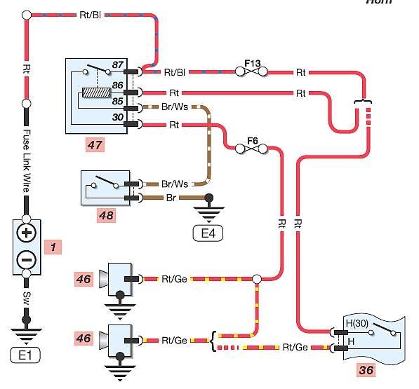
I agree with Foz. You can probably just use the current wiring for your new compressor using it in all together mode. If you are using the donor wiring loom then unless it was from a really low end model of Sierrra, (Horn not on steering wheel) then there is already a relay in the fuse box that is being used, and a fuse. So it would be odd to wire up another relay from the current relay. I attach the Sierra horn circuit diagram, might be of use if you have this loom. You can see the horn relay and the fuse F6 which is a 15amp fuse. 47 is the relay, 48 the horn button. 36 is the cheaper option on some models, horn on the stalk switches and no relay. By the way, the two diagrams that came with the new horns are to cover the two options that could be faced by the installer. The top diagram covers the case where the horn switch provides the power (+ feed) to the horn and the horn is the route to earth(-ve). The bottom circuit is the other way round, where the horn switch provides a route to earth from a horn that already powered from the positive. You will notice that the sierra is using this latter case, the horn switch 48 provides a route to earth.
-
Quite similar to what I am attempting. I have found the Haynes wiring diagrams quite hard to follow AND do not exactly match what I see in front of me. I am also using diagrams from a french persons cloud site that Google turned up. I put the link below to download the pdf. The diagrams are for all the electrics, and in there are coloured diagrams for the bits in the engine bay, they seem easier to understand and so far more accurate. (however the power input pin for the ESC2, pin 8, near the top is miss-labeled as pin 13). Anyway you might find these diagrams of some use. http://www.jeankule.free.fr/Pinto/1982-1989.pdf
-
I mostly agree with the above, when you get the V5C and registration number the car will have an official date of first registration. This will normally be around the date of your IVA pass, and I believe the first MOT is then due three years after that. However, you should not use the car on the road without insurance. Anyone that needs to take a car for an MOT must have it insured, third party insurance allows you to drive TO a station for a definite timed appointment by the most direct route. My car is on SORN at the moment. It must be insured to take it for an MOT before I can tax it again.
-
I just did a quick search for (2b AND Zetec), loads and loads of hits .... many of no use to you right now, but one thread is from someone in your position from a while back, some photos of the conversion, etc. Link To Thread