Sparepart
 RHOCaR Member
-
Posts
351 -
Joined
-
Last visited
-
Days Won
14
Content Type
Profiles
Forums
Events
Store
Community Map
Everything posted by Sparepart
-
I am attaching two docs, extracts from the manual, first is the spec of degrees advance etc.. for Pintos and the second is what you do, assuming that you are using the original ECU. Pinto-Ignition-Timing.pdfPinto-Ignition-Timing-Procedure.pdf
-
Perhaps you can obtain the Haynes manual for the Capri donor, it will have the wiring diagrams and colour codes of the wires. If there was no fog light then it will be apparent from the diagrams. Getting a copy of the manual would/will be useful for other questions about what wire does what that will probably arise.
-
Do a bit of digging on the web, the link below appears to be an example of what you are looking for, I looked no further, there may be other suppliers that have similar catalogues. https://www.frap-oem.com/technical-catalogue/?lang=en
-
I have the modified original Sierra wiper motor with the original loom, so like you have multi speed and park etc .... there are a couple of challenges when you use the Sierra wipers, I should mention, because they will not crop up with the Lucas wipers. 1. the Sierra wiper motor was designed to live outside of the passenger compartment, ahead of the bulkhead, thus has no need for any water proofing seal where the wiper shafts poke through the holes in that grill that runs along the under the windscreen of the Sierra. If you fit these wipers behind the bulkhead then you need to waterproof the shafts where they poke through the scuttle. You will have to figure out how to do this yourself. 2. I found that as standard the Sierra wipers park to the right and its hard to get them to both park neatly down, so one gets a bit in the way when looking through the screen (for the driver that is), so a modification to the way in which the driving arm attaches to the motor is required to have them park out of the way on the left. Unless of couse the kit that you bought included a solution for these challenges.
-
Perhaps the link below will help, apparently early blocks had 3 and later only 2, however the later block still lets you use 3. Read the blurb in the product description. https://www.retroford.co.uk/product/standard-timing-belt-kit/
-
If the Sierra loom was from a model up to 1987, then both dip and main use the same earth. I think that you probably have a sealed beam unit ? with the three spade connectors, in which case make sure that the contacts of the spades are nice and clean however since you swapped them then they probably have scraped cleaner by now. If its a bulb holder then youcan try swapping the holders?. The Main beam is a white wire the RHS one runs from fuse 15, the dip is a yellow wire, the RHS runs from fuse 17. Check the contacts on either side of the fuse holders. The LHS fuses are 14 and 16 resp, so you could measure the resistances from the fuse to the bulb connector on each side to see how they compare.
-
Are you considering the purchase of a four wheel drive car and replacing the engine ? For example a cheap Audi TT as per the link below. https://www.autotrader.co.uk/car-details/202203053231965
-
I agree, if the top plate is too low it could even block the carb. Years and years ago when I was a "boy racer" I took the filter off altogether and plonked a conical tube made from a yoghurt carton on the carb inlet, it made a great sucking noise on full throttle. just did not care about nasty thinks being drawn into the engine I guess.
-
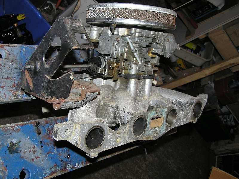
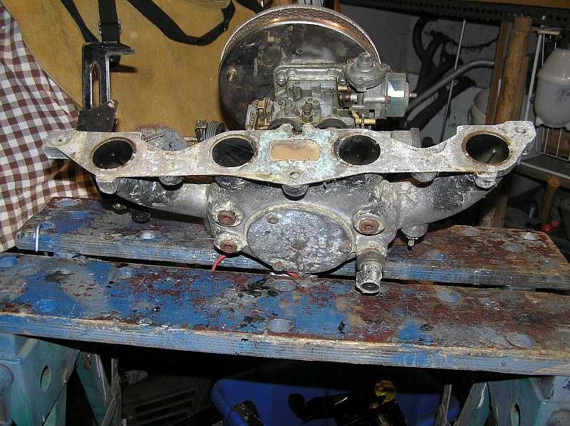
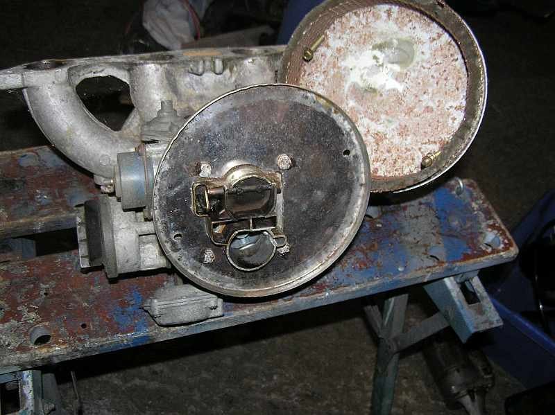
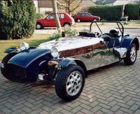
I dont have the same carb, however I bought a "Universal" pancake filter which was not very thick, it does not foul the bonnet. The drawback is that the surface area through which the air is drawn is limited, so the filter represents a hinderance to the ease with which air enters the manifold. This reduces the power of the engine. For this reason I am not totally happy with it, so am looking to reduce the restriction, by increasing the surface area of the filter, perhaps obtaining a much larger diameter pancake or making a large bore pipe manifold to bolt on top of the carb to which I will connect a wide pipe to a conical air filter mounted forward of the engine where the air intake is cooler. I attach some snaps of the filter that I am going to replace to show the sort of thing that can be done, just as a start to get the car on the road.

-
I am 46 minutes away from The Chalet, however the Exmo is not going to be on the road until later in the year. I'll keep this in mind till then.
- 1 reply
-
- 1
-

-
This topic has come up before. I did a simple search for "Brake" and "Servo" and near the top of the hits was the exact same question. https://www.rhocar.org/index.php?/forums/topic/48518-brake-servo-touching-manifold Browsing the others it looks like there have been several solutions, just fit a Ford Ka master cylinder, use the Sierra master without a servo. Have a look there is a wealth of information in past topics.
-
Here is a link to a site where you can download a copy of the service and repair manual for the Sierra, you might find it useful for lots of questions that you might have. https://musse67.mbnet.fi/Taunus/Korjausoppaat/ The wiring diagram for an 1988 model for lights is on page 13-40 (Diagram 2), there you can see the dip beam relay (37). You could check if the relay is the problem by making the connection that the relay would make by connecting pin 87 to pin30 which will provide +12v to the yellow wire that runs to the bus bar for both fuses 3 and 4. Each of these fuses should be 10 amps, so the relay needs to switch 20 amps. I'll pass on what a "continuous" relay is. I have a similar circuit, and have purched a fusebox that contains the sort of relay you need. It is rated at 30 amps for the switch when energised, and 40 amps for the switch when not energised (using the centre pin 87a, which is not connected in this application) I have measered the resistance between pins 86 and 85 and it is 80 ohms. Hope this helps. P.S. I looked at Halfords and this link is for the sort of relay you could try. https://www.halfords.com/tools/fuses-electricals-and-fixings/electricals/halfords-hef557-relay-12v-30a-5-pin-184161.html
-
You say the council have approved. I assume that you have checked for applications and approvals on their web site ?, I went to https://planning.leicester.gov.uk/ and searched at 9 Welford Place (for example) to uncover application number 20142317 for a change of use that was approved. For most applications you can see all the documentation, including any letters of objection, and the decisions of any any other parties (like parish councils) that might get involved. If you can't find a change of use approval at the property address then I would contact the council formally, be letter to enquire on what grounds they have permitted the change of use. It might be that it was publicised using notices through your letter box or pinned to the property boundary giving notice of the application, and you did not object.
-
I think that in order to run a business from a property that was only used as a residency previously, a change of use would be need to be approved by the planning authority. This is what a local in in my area had to do in order to use part of a garden as a car park. See the link below. https://www.planningportal.co.uk/info/200130/common_projects/9/change_of_use
-
Why not just not fit a windscreen until after all the tests have been passed?
-
I looked at the SORN status, and it says the MOT ran out in 2009 and that it is on SORN, so it's likely sitting around somewhere. I attach a copy of the SORN status. GOV.UK - Display Vehicle.pdf
-
I am sure that you have accounted for this, but I have to say that the shafts are not the same length, the nearside is shorter than the offside, so are you sure you have them on the correct sides ? or you have received two long shafts by mistake ?.
-
If you do sell seperately, then it would be a lot of work, but it could be worth itemising the parts of the kit that you have, at least the major bits. As mentioned prev in this thread some parts (if you have them) will be of interest to owners of other RH kits as well as Exmo owners. For example I believe the rear GRP wings are the same as as a series 7, you might have the branched exhaust manifold, the Cortina radiator, was a seperate steering rack bought, just the nut and bolt pack (looks well preserved) those copper brake pipes, the windscreen and frame, etc.. Simple thing like the nosecone badge. Lots of work though, but a pity just to throw away. I have a parts list with optional parts that was used on an Exmo order that I can post if it helps you look for/identify what is available.
-
I think that you will find that the engine in the Sierra is a CVH (1.8?), anyway it's not a Pinto. I think that the EXMO is designed around a Pinto so the CVH would most likely not be of much use to the kit builder. It was nice to see the photos of the EXMO bits, they bring back memories.
-
I see that you have another post about the stalk switch electrics. Perhaps you might find the Sierra electric circuit diagrams useful in answering your questions. You can see these in the service and repair manual that you can try and download from the link below. Of course this assumes that you are using the donor wiring loom for your 2b. Probably the four wires that you have in the dome lights are for earth, side, main and dipped beams. Looking at the wiring diagram, page 13.56 there should be a brown wire (earth for the side light), grey/Red (sidelight), Blue/Brown (common return for main/high and dipped beam), Yellow(Dipped beam feed), White(Main/High beam feed). Thats 5 wires, so I don't know what the sixth is, but you will see the colour and check with the diagrams. Also if the loom is still on the donor then of course you can just check out which ones are live when you operate the lights to confirm the diagram. https://musse67.mbnet.fi/Taunus/Korjausoppaat/ Just had another look, and if the sixth wire is Black it's probably for the fog light, which you will most likely not need (yet). Note that the High/Dipped beams do not appear to run straight to earth (brown) like the side light and fog light. They use the Blue/Brown common return.
-
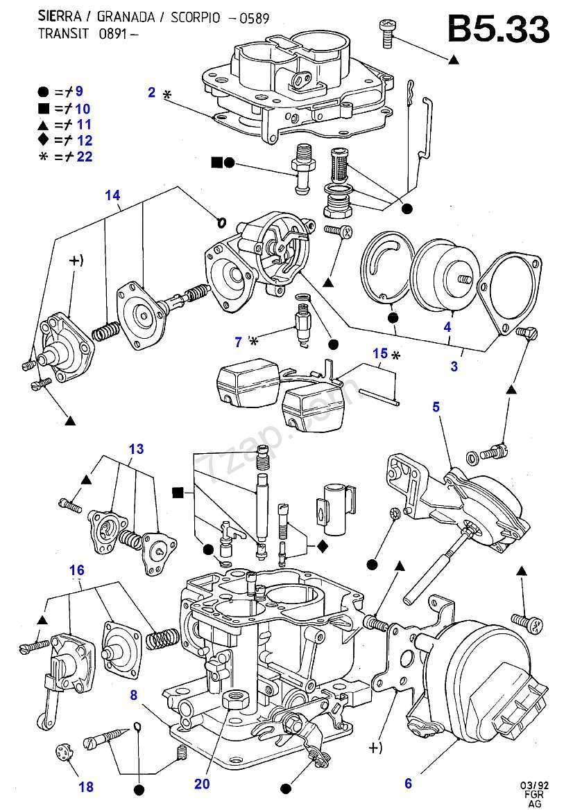
It does indeed explain, thank you very much for sharing this. In short when the engine is cold starting it prevents too rich a mixture (i.e. flooding) if the throttle is used to take revs above the idle rate. (I think). If the diaphragm fails then I assume there would be a tendency to get a rich mixture when driving with a cold engine, until the bi-metal coil expands enough to release the choke fully. So I notice (now) that some of the service kits that come from Germany do have this diaphragm, just not the one I bought, ho hum. .... just looked at the mechanism and I see it's the opposite of what I said above. When there is good vacuum below the throttle butterfly (idling) the diaphragm is compressing a spring that wants to release the choke. So if the diaphragm fails, the spring will constantly push the shaft that tries to release the choke (against the bi-metal coil that is hold in the choke on). This means that when the engine is cold it will tend to cut out if you try to rev it due to insufficiently rich mixture. There are so many parts to this carb, it looks like it was designed by the same committee that thought up a camel.
-
I am servicing a DFTH 30/34, it was well used and then been sitting around for a long time so its got a bit of corrosion on top of tar on the surfaces. All is going well so far, I have obtained a service kit and am helped by the exploded view that is attached below. I am puzzled by something. I see the automatic choke and how the bi-metal coil will unwind pressure on the choke butterfly etc this is item 4 in the diagram. I also see a part, item 14, which contains a diaphragm that is not in the service kit. Item 14 appears to be intimately involved with the choke, mounted at right angles to the bi-metal coil axis. I have not dissasembled this yet. Does anyone know what this part does? On the parts list is is "Kit-Choke Control" part number 6187682. Does it operate the choke at sometime after the engine is already hot. ?
-
I have replaced the driveshaft and pinion seals, luckily obtaining the correct size. I used the Haynes Sierra manual instructions for fitting, However during the process of Googling as much as I could about the Sierra Differentials I came across the link below, to Super 7th Heaven, which has more information about Sierra differentials than you ever want to know. You may have already found this, but just in case. Depending on what other components you might use on your car there is lots more information on this site. http://www.super7thheaven.co.uk/components/sierra_rear_differential/ I have downloaded as much as I can of interest from here, in case it all dissapears into the big bit bucket.
-
The obviouse diagnostic would be to use a compression gauge and look at how good each cylinder is. The manual says that at starter motor speed the pressure should be between 11-13 bar (all except engine code NAE) or 10-12 bar ( NAE code). Most people can't just open their toolbox and whip out a compression gauge though. Does a lot of air/smoke come out of the oil filler hole on the cam cover, which would indicate excess combustion gasses passing some ring(s). Unlikely but there might be too much oil in the engine. Does the smoke coming from the exhast small "oily" or "petroly" i.e. is the smoke just too rich a petrol mixture because say the float in the carb is leaky. Is there a petroly smell under the bonnet. Is any oil weeping out of the top of the dipstick tube, blown up by too much pressure in the crank case from poor ring(s). Also the "Crankcase Ventilation System" (manual say check every 12 thousand miles) could be inspected to see if the vent valve is blocked or the oil separator is all gunked up with oil.
-
When you do this, I would think that there is the opportunity to modify the rear ride height, either accidentally or by design. Others will know if this then will have a good/bad knock on effect of altering the camber of the rear wheels?. You have probably considered this already, however I thought I would mention it just in case.